On day 3 (day 1 here, day 2 here) I wanted to see if I could use a Raspberry Pi (3 or 0W) as the WiFi access point instead of my phone. Knowing I was taking a slight risk (with my time) I flashed a µSD card with the shiny new Raspbian Stretch. I tweaked all the things I normally tweak (e.g. remove Wolfram and LibreOffice, enable SSH, SPI, I2C, camera etc. – I may well add a camera to this at some point WJDK). Then I went through this excellent tutorial here, which I knew was written for Raspbian Jessie. I’d also done the tweak to reinstate the old wlan0 and eth0 names. I thought…
“I wonder if this tutorial will still work with Stretch?”
…but sadly it didn’t. I decided not to mess about though and quickly reflashed the µSD card with Jessie, fully updated/upgraded it and then the tutorial worked perfectly (I’m not using the ethernet bridging part). I don’t need the very latest distro for my bike lights. It’s never going anywhere near the internet. It will be its own self-contained little mini ‘intranet of things’.
Dev on Pi3B, Deploy to Pi0W
I did all this on a Pi3B, with the intention of switching it all over to a Pi0W for the final installation. Developing on the faster Pi3B is a bit easier, but the minimal size, power requirements & flexibility makes the Zero W perfect for deployment.
Poke, Prod. I Wonder if THIS Works?
Having got the WiFi access point working, I did some quick testing to see what the best method would be to send my “GET” calls. It turned out that using urllib2 within Python didn’t work, but using the simple bash command ‘wget‘ worked perfectly.
This meant I knew I could get the Pi to control the Wemos using the same mechanism I already had. Using ‘subprocess.call‘ in Python to call ‘wget‘ commands works perfectly.
It’s Time for some Python!
Using the apa class I wrote for the RasPiO InsPiring LEDs, I coded the animations and LED controls.
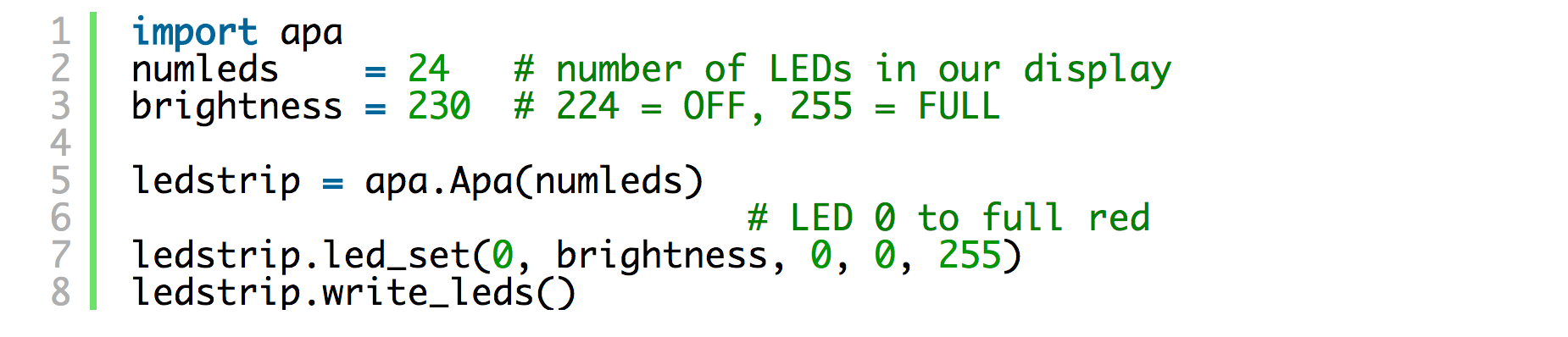
Code example of the RasPiO InsPiRing apa class
RPi.GPIO with four interrupts was used for the button controls. For left and right indicators I also used threading so that the ‘http GET‘ calls to the rear Wemos would run in another thread and not cause any delays in the front LED animation.
I also took the opportunity to recode the left/right turn signal indicators differently so that they would work ‘while pressed’ as they would need to for the real moped switch that I’d ordered. These indicator switches latch, so coding for a single, one-off press is not what is needed here.
It’s Here! The Switch is Here!
Then, later on, the moped switch arrived and I was able to ‘buzz out’ the wiring. It was really straightforward and turned out to be exactly what I needed. I did a test fit to see if it would go on the bike before spending time on it.

It fits! Moped switch in its intended location
Thankfully it trial-fitted perfectly, but placing it would require some thought (tomorrow’s problem) as it needs to be practical and ergonomic.
Let’s Test the Switch
So then I was then able to swap out the button board and hook up the moped switch to the Pi, via an InsPiRing driver board and breadboard with 10k pullup resistors on the button ports.
I’m delighted to say that everything worked really well. Changing to a Pi had completely…
- eliminated the need to involve my phone. We’re now just using a single Pi and a single Wemos D1 mini
- solved the timings issue. Using Python and threading, the system can now run front and back indicator lights that flash simultaneously.
- eliminated the failed BRAKE button presses. Now the buttons all do what they should, when they should. Perfect! Changed both hardware and software has done the trick.
YAY! We’re Nearly There
So at this point I was feeling like some real progress had been made and we almost have a usable system. All three of the issues from yesterday had been resolved by using a Pi and Python.
I couldn’t road test it yet because it was even more ‘prototypey’ than the previous breadboard. There were long wires all over the place, so I would have to install it properly. That would take me pretty-much the whole of day 4, as I wanted to miniaturise it as much as possible. So a custom driver board build was needed. I also wanted to make the installation as neat and tidy as possible, and this always adds to the required time.
You can find out more about the RasPiO InsPiRing LED shapes here