For a long time I’ve wanted to have a go with one of these 8×8 led arrays. I always thought they look like lots of fun. Searching around, I happened across Richard Hull’s Github repo, which provides a set of Python drivers and installation instructions for this 8×8 led array…

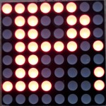
Max 7219 driven LED array – All on.
…which can be had, if you’re willing to wait a week or two, for a little over £2 ($3) delivered from Banggood
Assembly
It comes in kit form and takes about 10 minutes to solder up, if you’re not new to soldering. There are no instructions with the kit, but the silk-screen printing on the PCB shows you what goes where and there are some photos on the purchase page.
Drivers
Then you need to install the drivers (full instructions here)…
git clone https://github.com/rm-hull/max7219.git

sudo python max7219/setup.py install
Wiring
Make sure your wiring is right. This is a screenshot of Richard’s wiring table…

Wiring for LED array
Demo
Then all that’s left to do is run the demo program…
sudo python max7219/examples/test.py
…then ‘pop the hood’ and tweak it to make it your own, like I have in the video… :)
Nice Price!
Looking at the data sheet for the driver, to write different stuff to the two displays, it looks like you should just be able to write 32 bits rather than 16 before raising the chip select.
The data for the second display will be shifted through the first and out through the DO pin, so the first 16 bits will be in the second display in the chain and the second 16 bits in the first display. Not sure why that didn’t appear to happen in your test configuration. I’d have expected one display to be one line behind the other if the shifting was happening as I’d expect.
A four by four configuration would make a nice Conway Game of Life demo!
I don’t know either Derek, but I suspected that the outputs might have been just straight “passthrough” connections. I’ll get the multimeter out and check. I didn’t write the driver, and haven’t delved into it deeply enough to look at how it’s handling the SPI part (although it uses a different Python SPI driver from the one I normally use).
Will look into it.
Update: The Data lines (Din) aren’t directly connected, so it must be going through the chip. That’s hopeful :)
Wait, I looked at the video again. It is behaving consistently with the data being shifted through the first display after all. If you freeze the video at the 2:55 mark, you’ll see the left hand display show a lit right hand column while the right hand display shows an unlit right hand column.
What is happening is that the columns are being written to the first display and then shifted out to the second and written there too. Because it is refreshing the whole 8 columns, the second display appears to be showing the same as the first, but it’s not quite the same as the video reveals.
So yes, my earlier suggestion will almost certainly work, just write 32 bits before activating the CS signal and you’ll get your displays showing different patterns.
Hi
On the strength of this tutorial I went out and bought 4 of these board! :)
Just wondered if you advanced the code any further to allow the use of multiple boards as though it was one display?
Cheers
Chris
No. Been busy on other things I’m afraid.
Hi Chris,
I don’t have any of these displays, but my suggestion will scale to 4 boards. Just write 4 words at a time. The first word written will appear on the last display in the chain. Write all the first rows, followed by all the second rows etc. A nested for loop will do the trick.
Derek
thanks – will the daisy chained power from the Pi be enough to drive all 4 boards?
Nice review, Alex. For that price, everyone should have a go!
> will the daisy chained power from the Pi be enough to drive all 4 boards?
I could not find enough data on the device to answer that. The maximum current is 500mA per board, but I doubt it draws that much. You’ll need to measure the current drawn by one display and see.
It will also depend on the quality of your Pi power supply and on how many of the LED’s you need to illuminate at once (I’d calculate on them all being illuminated and then you can’t go wrong).
Of course, it is possible to provide a separate 5v supply to the displays if it comes to that.
How to provide 5V externally while it is connected to rpi?
Thanks for the help so far. I’m not having much joy though. When I come to install I get this
pi@raspberrypi ~/max7219 $ ls
build doc examples README.md setup.py src
pi@raspberrypi ~/max7219 $ sudo python setup.py install
running install
running build
running build_py
running build_ext
running install_lib
running install_egg_info
Removing /usr/local/lib/python2.7/dist-packages/max7219-0.0.1.egg-info
Writing /usr/local/lib/python2.7/dist-packages/max7219-0.0.1.egg-info
pi@raspberrypi ~/max7219 $ sudo python examples/test.py
can’t open device: No such file or directory
Any ideas?
I’ve got one of these http://www.raspberrypi-spy.co.uk/2013/09/how-to-setup-the-pi-lite-led-matrix-board/ set up and running on another Pi, no probs.
Cheers
Chris
Have you got SPI set up on this Pi? Follow the full instructions link in the article above, if not. Or find spi enable instructions here…
https://raspi.tv/how-to-enable-spi-on-the-raspberry-pi
Sorry recently I have the same problem and i don’t know how to fix it. it just shows ‘can’t open device: No such file or directory’, but i’m sure i’m in the right directory and it worked several days ago. The problem just suddently appears… Do you have any suggestions?
Have you done an upgrade recently? The kernel in Raspbian now uses DeviceTree, so the process for enabling things like SPI works a little differently:
http://www.raspberrypi.org/documentation/configuration/device-tree.md
https://github.com/raspberrypi/firmware/blob/master/boot/overlays/README
Excellent!! Many thanks – works like a charm now. Now I’ve just got to work out the bit about daisy chaining them together to get the text flowing between them
Thanks again
Chris
Sorry for all the questions but where can I find out more about the commands I can throw at the display?
thanks in advance
You’ll have to look in the Readme or in the files themselves
I have also tried this but I cannot get it to compile successfully, I seems to be missing the build folder in the max7219 dir.
This is what I get when I run setup.py
pi@raspberrypi ~ $ git clone https://github.com/rm-hull/max7219.git
Cloning into ‘max7219’…
remote: Counting objects: 48, done.
remote: Compressing objects: 100% (26/26), done.
remote: Total 48 (delta 17), reused 47 (delta 16)
Unpacking objects: 100% (48/48), done.
pi@raspberrypi ~ $ ls
Desktop max7219 ocr_pi.png python_games
pi@raspberrypi ~ $ cd max7219
pi@raspberrypi ~/max7219 $ ls
doc examples README.md setup.py src
pi@raspberrypi ~/max7219 $ sudo python setup.py install
running install
running build
running build_py
creating build
creating build/lib.linux-armv6l-2.7
creating build/lib.linux-armv6l-2.7/max7219
copying src/led.py -> build/lib.linux-armv6l-2.7/max7219
copying src/font.py -> build/lib.linux-armv6l-2.7/max7219
copying src/__init__.py -> build/lib.linux-armv6l-2.7/max7219
copying src/transitions.py -> build/lib.linux-armv6l-2.7/max7219
copying src/canvas.py -> build/lib.linux-armv6l-2.7/max7219
running build_ext
building ‘max7219.spi’ extension
creating build/temp.linux-armv6l-2.7
creating build/temp.linux-armv6l-2.7/src
gcc -pthread -fno-strict-aliasing -DNDEBUG -g -fwrapv -O2 -Wall -Wstrict-prototypes -fPIC -I/usr/include/python2.7 -c src/spi.c -o build/temp.linux-armv6l-2.7/src/spi.o
src/spi.c:20:20: fatal error: Python.h: No such file or directory
compilation terminated.
error: command ‘gcc’ failed with exit status 1
pi@raspberrypi ~/max7219 $
Have you any idea of what I’m doing wrong?
Thanks,
Andrew
You probably just need to:
sudo apt-get install python-devand then try again :)
Thank you, that worked :-))
Hi All
Me again. I’ve got two of these running together as shown in the vid – still can’t work out how to make the ‘one big screen’ though – not sure what ” it looks like you should just be able to write 32 bits rather than 16 before raising the chip select.” in terms of the libraries I have in the project.
Cheers
Chris
This could be helpful
http://www.instructables.com/id/16×8-LED-dot-matrix-with-MAX7219-module/
Hi All,
Try as I may I cannot get the following command to work:
pi@raspberrypi / $ git clone https://github.com/rm-hull/max7219.git
fatal: could not create work tree dir ‘max7219’.: Permission denied
I have tried “sudo apt-get install python-dev”, rebooted and retried but get:
pi@raspberrypi / $ sudo apt-get install python-dev
Reading package lists… Done
Building dependency tree
Reading state information… Done
python-dev is already the newest version.
0 upgraded, 0 newly installed, 0 to remove and 0 not upgraded.
I have also successfully completed:
sudo nano /etc/modprobe.d/raspi-blacklist.conf
I suspect it is related to missing spi files in DEV directory but cannot work out how to overcome it.
Any suggestions?
The git clone is failing because you’re trying to run it from the root ‘/’ directory, which you don’t have write permissions to (and which you shouldn’t be doing anyway!)
Change back to your home directory (likely to be /home/pi/ ) with just a simple ‘cd’ and then your ‘git clone’ command will work.
Hi All,
Have successfully loaded: git clone https://github.com/rm-hull/max7219.git
But have now hit a road block trying to run: sudo python max7219/setup.py install
pi@raspberrypi ~ $ sudo python max7219/setup.py install
running install
running build
running build_py
error: package directory ‘src’ does not exist
I have run: sudo apt-get install python-dev
rebooted & retried but no improvement.
PiGlow functions okay so SPI is set up correctly.
Any ideas what to try next?
Thanks
Nigel
I don’t know what the problem is, but Piglow uses i2c not spi, so don’t assume that spi is set up right based on that.
Try changing to the correct directory first, i.e.
cd max7219sudo python setup.py install
Thanks Andrew, that worked a treat! :-)
Follow-up question if I may; is there a command similar to “GPIO.cleanup()” to turn off the spi pins once you have finished or interrupted the programme?
Thanks
Nigel
I could be wrong, but I don’t believe that’s necessary for SPI. SPI (and i2c) is a serial bus so the pins only change state while the message is being sent, and as soon as the message has been sent (which takes almost no time at all) the pins go back to their ‘idle’ state.
But I guess you’d need to ask the person who wrote the max7219 driver (rm-hull) to be sure ;)
That worked for me too thank you.
Hello,
I have a question.
I used this code:
/
import max7219.led as led
import max7219.canvas as canvas
import max7219.transitions as transitions
import time
from random import randrange
led.init()
led.show_message(“Hello world!”, transition = transitions.left_scroll)
/
It works like a charm, but I’m having a question, which will probably sound stupid. What is line to lit them all on.
I know it’s 0xFF that lit them all ON and 0xCC should turn them OFF.
I just don’t know how to add that here. I want to turn them all ON after it says Hello world!
Sorry,
I figured it out.
I used line
led.send_byte(0xff, 0xff)
:)
help me!
i can’t run program test.py
root@raspberrypi:/home/pi/max7219# python examples/test.py
Traceback (most recent call last):
File “examples/test.py”, line 3, in
import max7219.led as led
And how can use 2 board for display? thanks
Sounds like the drivers are not in the same directory as the python script.
Thanks! after reinsall, it work perfect. Could you help me how to use 2 board for display!
I hope someone else can help you. I haven’t done it, so don’t know how.
Need to “cd max7219” BEFORE the setup is run!
Surely not if you use the command I gave you, which includes it in the path?
sudo python max7219/setup.py installThat may work in some cases (I can’t comment on this particular library as I don’t have the hardware), but I believe there are also some python setup scripts which look for files in the current directory; so in general I think ‘cd’ing first is the recommended option. Always good to get into good habits ;-)
Fair enough. It was a while ago, so I don’t quite remember, but I normally post the commands I actually use.
Hello, thank you very much for these instructions. After I had to change the local path in the setup.py and edit the blacklist, the test.py startet working nicely.
As a thank-you I’d like to share my tiny 8×8 scrolling digital clock for the raspberry using your library. I use a slightly different concept of the font, stored in a python dictionary.
Have fun! – McPeppr
#!/usr/bin/env python import max7219.led as led import max7219.canvas as canvas import time font5x3 = { # python data type dictionary for the pixelfont "0" : [0b01110, 0b10001, 0b01110], # "0" "1" : [0b10010, 0b11111, 0b10000], # "1" "2" : [0b11001, 0b10101, 0b10010], # "2" "3" : [0b10001, 0b10101, 0b01110], # "3" "4" : [0b01110, 0b01000, 0b11111], # "4" "5" : [0b10111, 0b10101, 0b01001], # "5" "6" : [0b01110, 0b10101, 0b01000], # "6" "7" : [0b10001, 0b01001, 0b00111], # "7" "8" : [0b01010, 0b10101, 0b01010], # "8" "9" : [0b00010, 0b10101, 0b01110], # "9" ":" : [0b01010], # ":" "-" : [0b00100, 0b00100, 0b00100], # "-" "|" : [ 0], # one blank line " " : [ 0, 0, 0] # space } # you can create additional letters def creatematrix(text): text = str(text) matrix = [] for i in range(len(text)): # write complete pixelmatrix in a buffer if text[i].upper() in font5x3: # check if dictionary entry exists matrix = matrix + font5x3[text language=""[i""][/text].upper()] # add letter; upper() for reduced font matrix = matrix + [0] # separator/space return matrix def drawmatrix(matrix, up, left): for i in range(8): # fill the 8x8 matrix buffer if up < 0: canvas.gfxbuf[i] = matrix[(i + left) % len(matrix)] <> abs(up) led.init() horz = 0 vert = -2 led.brightness(0) # 0, 3, 7, 15 seems to work while True: t = [int(time.strftime("%H")), int(time.strftime("%M")), int(time.strftime("%S")), int((time.time()*1000) % 1000)] if (t[3] % 500) < 250: # switch for the blinking colon m = creatematrix(str(t[0]) + ":" + str(t[1]).zfill(2) + " ") else: m = creatematrix(str(t[0]) + "|" + str(t[1]).zfill(2) + " ") drawmatrix(m, vert, horz) horz = (horz + 1) % len(m) # scroll left canvas.render() time.sleep(0.05)Hi, I want try to configure two 8×8 matrix with max7219. It’s just enough to connect the chip as described below and automagically all start to works? …or I need to change something in the code to ‘declare’ the second chip?
*********
This board has also five upper pins for connecting multiple panels in longer chains. If we connect another board to the five top pins we will get two boards displaying the same thing. If we want to get a longer line then we have to connect all the SPI pins to the microcontroller except DIN pin. First board DIN pin goes to microcontroller, while next board DIN pin goes to DOUT pin (opposite pin on top of the board)
A few people before in this thread have asked about daisy-chaining several of these boards together to use them as one long display. Derek Campbell suggested it was simply a case of writing more bits before latching the data with the CS signal. I don’t know if anyone here is still interested in this, or if you’ve already worked it out, but for the record, this is how I have managed it.
I have confirmed that Derek is correct, but (rightly or wrongly!) I concluded that it was not easy to do this with the functions provided in Richard Hull’s MAX7219 library which I believe were intended just for one board. I think (more from experimentation than from studying the C code in his library) that that library’s send_byte() function always raises CS after each 2-byte (register-data) pair, so it was not possible to send data to a matrix along the daisy-chain without it also appearing on the matrix or matrices closer to the Pi.
What is required to get independent control of each matrix in the daisy-chain is either to:
– send a long string of 2-byte words (register-data) to push the required data through to all of the matrices at once, before raising CS (thus re-writing the relevant column in all of the matrices each time any of the LEDs is to be changed), or
– send a string of the same length, but filling the words destined for the other matrices with zeros (0,0) which is interpreted as ‘no operation’ by the destination matrices.
Either of these approaches requires sending a long string of bytes before changing the level on the CS pin.
To do this I didn’t use Richard Hull’s library, but instead I used what I think is a more generic SPI library, spidev, which includes a function which does just what I required (I installed spidev following the instructions I found at http://www.100randomtasks.com/simple-spi-on-raspberry-pi).
I have re-written Richard’s excellent library functions using the basic spidev library function, and, inspired by his work, extended them to provide a range of functions to drive a daisy-chain of MAX7219 boards. For good measure, I have included some more 8×8 fonts that I scavenged from the internet, and have a demo script (for an array of 8 boards) that shows what can be done with the re-written library. Apart from the spidev modules which I downloaded, all of this is written in Python and (I hope) easy to use and adapt. If anyone is interested I can make these scripts available – I’m just not sure the best place to put them. (I did look at Github, but that looked rather involved if all I wanted was a public repository for some code – any ideas?)
Incidentally, I bought my 8 MAX7219 boards for ~UK£1.40 each from one of my favourite Chinese EBay sellers, and power them from a separate 5v breadboard power supply (another EBay special from the same seller), not from the Pi. I think this makes for a really cheap display board which is also a fun project to put together and use.
(Apologies for the long post)
I’m really interested to try your code for my project! I’m waiting with impatience your code. Please share it.
Regards
OK, I’ve tried to upload my library to Github, but I’m new to that so I hope it’s worked (I’ve just corrected some errors in my upload and I think it’s now OK – apologies if any remain). The link is: https://github.com/JonA1961/MAX7219array
You need as a minimum to download the MAX7219array.py (function library) and MAX7219fonts.py (fonts data) files to a folder. The demo file is MAX7219array_demo.py if you want to have a look at that (see notes below). I’ve copied all the comments from the various files into one documentation file (also a Python script, although it does nothing) as MAX7219array_ReadMe.py. To download all of these files in one go, enter the following on your RPi at the command line prompt:
git clone https://github.com/JonA1961/MAX7219array.git
This will create a folder in your current folder called MAX7219array and copy the files from Github into it.
Note that the demo script is written for a set-up of 8 MAX7219 boards. It should run even if you have a different number but will not (obviously) display exactly what I intended it to. Looking at the code however you should see how to adapt it for your purposes, or how to use the library functions.
Before you use these files, unless you already have it installed on your Pi, you need to install spidev. I suggest you follow the same instructions that I used from http://www.100randomtasks.com/simple-spi-on-raspberry-pi (ignore the references to the TLC549 ADC but follow the instructions as far as the bit that reads “With all the setup now complete, it’s time to write some python”)
The wiring setup I used for the MAX7219 boards is documented in either the MAX7219array.py or the MAX7219array_ReadMe.py files. You also need to set the value of NUM_MATRICES in the MAX7219array.py library file to the number of MAX7219 boards you have in your daisy-chain.
To run the demo, in the MAX7219array folder, enter the following at the command line prompt:
python MAX7219array_demo.py
To use the library file as a simple command-line utility to scroll a message on the array:
./MAX7219array.py ‘Your message goes here’
Have fun, and I welcome your comments
Hi Jon, it would be possible using the SPI of Wiringpi library? I’m using a total of 16 MCP23s17 on channel CE0 CE1 (8+8). Could be possible to add on the same bus (CE0, for example) the 8 devices and use it with Wiringpi?
The short answer is that I don’t know. I’m afraid I haven’t yet had time to look into WiringPi (just too many things to do with the Pi in the 3 months I’ve owned one!), although its definitely on my list when I get a chance.
From a very quick look, I can see that there are some SPI functions in the Python wrapper for WiringPi, so if these provide exactly equivalent functionality to the two I’ve used from spidev [ xfer() and xfer2() – descriptions at the bottom of the webpage that I linked on 100randomtasks.com] then it should be a simple matter to replace the 2 occurrences of these in my MAX7219array.py library with the WiringPi equivalents. I may look into this sometime. When I was trying to get SPI working, I’m afraid I took the path of least resistance – it was so easy to set up spidev that I didn’t look any further!
I’m not sure from your description exactly what your current setup is (do you want to use several MCP23S17s at the same time as a chain of MAX7219s?) I thought you could only independently address devices on unique bus & CE combinations – so if you are already using both CE0 & CE1 on the one SPI bus, is it easy to use another SPI device on the same bus? (Although if you used the similar MCP23017s instead, you could address those by I2C, leaving the SPI bus free for your MAX7219 array?)
Thanks for all the good work here, I have connected 12 of these together and had some fun adapting your code for new effects etc.
But I have a problem if I connect more than 12 units or if I extend the cables to more than a few inches.
Basically I see random data on the displays, so it looks like the signal is getting corrupted, I think it may be a hardware limitation of the SPI ports?
Can someone suggest a way to increase the cable length IE some kind of “booster” or filter etc ?
Thanks
Another possibility could be that you are simply exceeding the capacity of whatever power supply you are using to drive the boards. See post #17 below – this causes the boards to behave unpredictably and they have to be reset to fix it, they don’t just work properly again as soon as the current demand drops back into capacity.
Its not a lack of current as I have it connected to 3.3volt output of an old ATX Pc power supply, this is also running the PI on the 5volt output, the 0 volts are linked of course. They work perfectly on around 6 inches of cable from GPIO ports but if I extend that to even 24″ I get nothing readable on the displays, they do light up randomly suggesting to me that the data is corrupted.
I have tried running at 5volts without a level converter (I think this is safe for the PI as all signals are outgoing ?) but no difference.
I also tried grounding the signal lines at the far end with 470ohm, I didn’t want to go to low as it would load the GPIO lines.
I thought I might try using a level converter such as SN74LVC245AN and possible lower value end of line resistors.
If anyone has any other suggestions or a working solution, as I’m sure I can’t be the only one who has tried moving the display a bit further away from the PI ?
Hey guys,
Well before i try and get some work done with these i wanna ask some things. It’s been brought up before but never really answered. I wanna daisy chain 8 of them and really dont know if i can power it from the Pi then or i should use a different power supply . Mine has 700 mA which might not cut it right? Also read that some use a level shifter is this necessary cause that would make my project a little bigger and it might not fit into what i was supposed to make it fit in :) I might also be editing some code to make 2 rows of 4 a possibility if that’s not already been done.
Anyway thanks for the help anyone can give me.
I strongly suspect you’ll need a separate PSU.
Level shifters are very small (and you’ll only need one, connected to the Pi) so shouldn’t add any bulk to your project.
BTW I just spotted this over on the Pi forums: http://www.raspberrypi.org/forums/viewtopic.php?f=63&t=82921
32×32 would be to big also i’m not familier with c so that would be a big learning curve before i might get this done. My case for this is very cramped but i might be able to find a bit of space for a small lever shifter. Thanks for the input.
Power
I found that I needed to use a reasonably powerful external power supply to the array of 8 MAX7219s. The total current drawn by the array obviously depends on:
– the number of MAX7219 boards
– the brightness you set using the specific register
– the total number of individual LEDs you have lit at any one time.
When I was experimenting with these boards I did some measurements and found the following (broadly consistent with the datasheet):
– with no LEDs lit, the array of 8 boards drew 50mA;
– with 128 LEDs lit in total (perhaps a reasonable average working assumption of 25%) it drew between 80mA (brightness 0) and 620mA (15=max brightness);
– with 512 LEDs lit (ie all LED on each board) it drew from 140mA (0) to 1760mA (15).
If you power the array from the Pi and the array draws too much current (eg because you’ve attempted to display some text or patterns that needs too many LEDs lit), your Pi will of course cut out. As a 1A suppy is recommended for the Pi alone (other peripherals like wifi dongles take some), your 700mA supply sounds unsuitable to drive more than 1 or 2 MAX7219 boards from. You can obviously use a lower brightness setting to try to operate within your PSU rating, but that depends on what light conditions you want to use the display in.
Another consideration is that, even if you use a separate PSU for the array, if the array draws more current than can be supplied, the whole array will not work properly until it is reset. (On mine, whole boards switch on or off and don’t respond to any instructions until they are reset.) So you want to avoid any possibility of a current overdraw, rather than expecting that it will just fail to display momentarily and then recover.
I have mainly used a separate 700mA (rated) breadboard power supply for the array, but it is easy to overload this. I found that if I asked for more than about half the 700mA rating (that’s just 256 LEDs lit at brightness 3) I could get it to cut out (in fairness, the breadboard PSU was very cheap!). It depends what you are displaying of course – most text will not light up even a quarter of the LEDs at once, and the breadbaord PSU will work adequately.
Level shifter
The MAX7219 datasheet seems to specify a minimum logic-high input voltage of 3.5V but I have not found any need to use one of these.
Different layout of boards
When I wrote my library functions, I did consider including the facility to have the boards arranged differently than in one long line. In the event, I didn’t, mainly because my boards (and all the similar ones I’ve seen) will only fit right against each other sideways – the layout of the PCB prevents them being put above or below each other without separating the actual 8×8 LED matrix from the driver boards and having a mess of wiring joining them. I decided that if I was going to use them any other way I’d just use some intermediate python functions to translate the ‘real’ positions of each board/LED into the ‘virtual’ one that my library functions expected.
oops, that was meant to be a response to post #16
Thanks for the explanation. That has really helped me a ton. I’m not that great in the hardware stuff for the pi but really wanna learn and the only way for that is to try. On the other hand i’m fairly good at software and programming so i will figure the layout of the boards when i get to that part. About the layout i would be using a breadboard for tests but i would be using a prototype pcb or was even thinking of creating my own pcb (or order it) so i could have 2 rows of 4. But it depends on how well all of this works on the breadboard first. Again thanks for your help.
Hi all!
Thanks Jon for your fantastic python library! I was able to drive 12 MAX7219 LED matrices. I powered the LED’s from my 5A lab power supply at 3.3V with a common ground. Your library made it all so much the easier! In the below video you can see the current drawn (in the background) whilst running Jon’s demo.
I am going to obtain a few more LED matrices and expand it some more!
how to get its program scetch
Thank you Jon, for this library.
I just bought 10 LED dot matrices, for chaining them together, but they are chained directly. Now I got mirrowed characters and a wrong direction, what should I do?
Thank you sprossi1
You’re welcome sprossi1, I’m glad you liked it (and TryTryTryAgain too for the kind comments).
Re the problem you’re having sprossi1, the first thing to do would be to check the way you’ve connected up your matrices – see the description in my MAX7219array_ReadMe.py file. Note especially that the RPi SPI.MOSI pin is connected to the DIN pin on the matrix at the RIGHT end of the row. Also, I’ve realised now it may not be clear from my documentation, but I have each board arranged so that the IC chip is BELOW the 8×8 display, not above it. Your description possibly sounds as if you have connected them from the right-hand end just as I have, but with each of your boards the other way up to mine.
Hope this helps!
I bought this dot matrix from electrodragon.com http://www.electrodragon.com/product/dot-matrix-chain-display-kit-max7219-v2/
My Matrix is directly chained to another.
And now, if I am testing the lib, I got mirrored characters, and when the horizontal scrolling should start, It scrolls up and down.
My thought was, that this lib is written for a matrix, where the PINs are obove and below the matrix and they are connected sideways.
But is there any possibility, to recode the lib? I looked into the source, but could not find any solution.
Thank you for your help.
sprossi1
That looks like a clever design of board, so that the display matrices can be put right next to each other in 2 dimensions, rather than just in a row like mine (which are like the one shown at the top of Alex’s article above). But it sounds as though the assignment of rows & columns in the matrix to registers in the MAX7219 is different to that in the other design of board, which is what my library was designed for. It might be possible with some analysis and experimentation to work out how to change the library to drive the electrodragon board, but I’m afraid I haven’t got time to do that.
Hello !
excuse me but , have you a C or C++ version for this code ? please ! *_*
Sorry I don’t. I don’t know much C, just a little bit of C++ that I picked up from Arduino sketches.
But really you’d be better off asking the guy who owns the Github repo anyway RMHull.
[…] on these fine instructions by raspi.tv I wrote some tiny python code to display a scrolling digit clock on an 8 by 8 LED matrix using the […]
Hi All,
how to get in the JonA1961 library german fonts like “Üü Öö Ää ß” ?
Please Help
thanks
If you can represent each character in your font on an 8×8 grid, and you understand how each column in that grid can be represented as an 8-bit number, then you should be able to add either extra characters to an existing font, or add an entirely new font. See the comments in MAX7219fonts.py for details of the data structure, and look to see how the existing characters in the fonts are represented – although I can’t give you detailed instructions; you will have to work that out yourself. I’m not very familiar with the treatment of accented characters etc in linux-based systems, so I’m not sure if you will be able to convert these straight from text, but if your special characters convert in Python with ORD() to an integer in the range 128-255, you probably just need to add data representing those characters into one of the existing fonts at the appropriate location.
I hope this gives you enough to get you started – good luck and have fun experimenting!
Thanks Alex – I used this and Jon A’s library to get me going with my Raspberry Pi powered LED Twitter Ticker: http://youtu.be/rwFFO-g_r-k
hello i have the Jon A’s program and two MAX7219 and i would like to start the program at the start of the raspberry pi, i try with the following ile : /etc/rc.local but it doesn’t work, have you got another idea ? :s
http://www.raspberrypi.org/documentation/linux/usage/rc-local.md
For other options, try searching google for e.g. “linux run script at startup” ?
Thanks it’s now running :)
Hi Dofrey,
I started to convert JonA’s python library to C++. I use it in a project with 8 matrices and so far it works. I din’t test it yet with more or less matrices. If you are interested, you can download the code here: https://github.com/MikeHg/MAX7219MATRIX
Best regards,
Mike
Hi, Is it possible to display a basic image on this display I have it working so it displays text but I don’t know how I would display a basic image e.g. a line or a box etc
A quick look through the documentation finds http://max7219.readthedocs.org/max7219.html#max7219.led.matrix.pixel
I guess it shouldn’t be too hard to use https://pypi.python.org/pypi/Pillow/2.8.1 to load in a black-and-white 8×8 image, and then make 64 pixel() calls to set each of the LEDs on or off as necessary.
Thanks! ill try this
Hi Oliver,
Of course you can. Jon’s library includes already some graphic functions (gfx) that allow you to draw on the display.
Regards,
Mike
Ok I’ll have a look, Thanks!
Hello! I have a problem with the led mtriz, to be specific in q’m talking’m going to shows a video of my led matrix and see the result obteve.Se know of any solution please tell me what I’m missing. https://www.youtube.com/watch?v=8FureD0Ix9g
Hello João, Sorry but I can’t watch your video. Youtube says it’s private…
I’m sorry I forgot to put it in public. But now is already in public rsrsr
I had a look at your video but it is hard to say what went wrong. One possible source of problem is that SPI on raspberry has 3.3V whereas the LED module usually runs with 5V. I personally use a level shifter.
Another problem of course can be the wiring which is hard to tell from video. Probably a foto would help here.
Hi there. I just did a rip-upgrade and my script for the 8×8 led isn’t working, when i reinstall the max7219 i get various errors.
import max7219.canvas as canvas
ImportError: No module named canvas
please help.
Mine is having the same issue; it seems the canvans.py and some others were left out of the git rip.
transitions is missing to; and I can’t find any other places on github that has them…
Going a little nuts here: I get a “No module named max7219.led” error despite (apparently) successful install of the max7219 and python-dev libraries. Python no happy trying to use the module at all!
Is it in the same directory as your python script?
No – can’t find it anywhere so something got missed on the installs somewhere.
I have the same issue. Same exact error.
It is because of a path issue. I faced the same problem. Here is what I did. Copy examples/matrix_test.py one level up. Then run it.
After copying, my folder loos like the following
pi@raspberrypi ~/max7219 $ pwd
/home/pi/max7219
pi@raspberrypi ~/max7219 $ ls
docs examples LICENSE.md matrix_test.py max7219 README.md setup.py
pi@raspberrypi ~/max7219 $
pi@raspberrypi ~/max7219 $ sudo python matrix_test.py
Hi,
I’m rather new on RPi and totally new on max7219.
I have two questions.
Is it right that after wiring the device and before any program is running it’s already lighting up?
I had the same problem with the test.py file as mentioned before in this thread and after moving the Python-file one level up there were no errors. The program seems to run ok but there is no reaction on the matrix.
What van cause this problem?
Paul
Can i draw custom shapes and light up individual led using this python library?
I initially came across the ‘No module named max7219.led’, and copied matrix_test.py up one level.
This then gave me ‘No module named spidev’.
I then:
git clone git://github.com/doceme/py-spidev
sudo apt-get install python-dev
cd py-spidev
sudo python setup.py install
cd ~
cd max7219/
sudo python matrix_test.py
This then displayed the test lighting on the display. Not sure how much of the above was required as I took information from other web pages, but worked for me.
Hi any one have characters “H” dots matrix code for raspberry pi
https://github.com/rm-hull/max7219/blob/master/max7219/font.py#L108
Thank you Andrew … i will try to execute it
is this code works on 8×8 dots matrix?
Yeah, provided you’re using the rest of the max7219 software correctly, then it the line I linked to should represent an 8×8 matrix looking like:
##__##__
##__##__
##__##__
######__
##__##__
##__##__
##__##__
________
The font seems to store characters by columns, rather than by rows.
Thanks for a great article, successfully got me off the ground. Even managed to get a four panel version working and scrolling along all four as if it were one.
http://www.banggood.com/MAX7219-Dot-Matrix-Module-4-in-1-Display-For-Arduino-p-1072083.html Not bad for 7 quid.
Ended up looking like this:
https://youtu.be/_D6RMk-ZtRs
If anyone wants the Python code, I can supply it.
A link to your code (or zip via PM?) would be great, thanks!
could you supply the code thkx
i am really confused. i just got the led module and i have done everything i can but it just comes up with “python: can’t open file ‘max7219/examples/test.py’ : [errno 2] no such file or directory”
You need to update some stuff. The imports and directory structure don’t match and I am not up to knowing what to do to make it work. Can you please test this and update for Python 3?
It’s not my stuff to update. It’s RMHull’s. You should submit a pull request on github or he’ll probably never see your comment.
According to https://github.com/rm-hull/max7219 it already supports Python3 ?
And it would be more appropriate to create an issue on github, as pull requests are for submitting code improvements, not requesting features ;-)
I wasn’t sure to whom Mike Morrow’s comment was directed – I wondered if it was me, re the library I offered in post #15 above, particularly as that was written for Python 2.7 not 3.
It is was by any chance me (but I might also suggest this if he is going to message RM Hull) then I would tactfully suggest that Mike might wish to rephrase his comment somewhat. Personally I don’t think either RM Hull or I NEED to do something, just because Mike isn’t up to knowing what to do with something that he has been offered free of charge. Alternatively, he could do what I did (and many others like Alex and RM Hull do) and put some time in himself to learn how to make it work, and then offer his enhancements in turn to others online. I even mentioned in the Readme document that my library was written for 2.7, and provided some pointers for what might need changing for Python 3.
Yes – asking for help in a way that makes people want to help you is a skill. When someone tells me I NEED to do something in that way it instantly sets off an inate reaction (probably caused by a genetic trait related to ‘engineering tendencies’) that could be named “the awkward bastard reflex”.
Generally, I find I often get great help from people by…
I find that when I do this, people are more than happy to help – often going far further than I could have asked or expected.
Haha, spot on, Alex. You must be psychic re the ‘engineering tendencies’! And I’m sure I’ve also been called an awkward bastard at some point as well :-)
In case Mike is trying to use my library and comes back to read this, I’m afraid that although I follow the comments on this thread (and try to give helpful pointers when people ask questions about my library), I haven’t even switched on my Raspberry Pi in the last 2 years, and regrettably am unlikely to be able to find any time for it in the foreseeable future. (I know, I need to re-prioritise my life!) So I probably won’t be doing any work on my library anytime soon.
BUT it really shouldn’t be too much work to make the necessary amendments to the code to get it to run on Python 3. In the Readme file I suggested that it MAY be limited to altering the Print statements, although I can’t guarantee that there isn’t anything else. I think those are limited to the last 20 or so lines, and anyway are all concerned with providing a helpful message, so as a quick investigation, you could just comment them out to see if that lets the code run. For a more permanent change, you could find about the differences between Python 2 & 3 in the way the Print statement works (I think they’re fairly straightforward), then make the necessary changes to those statements.
Alternatively, just run it on Python 2 first – I assume that’s still available? – to see if it does what you want.
I’m afraid I’m not sure what the issue is with the import and directory structure and haven’t got time to look into that, but would have hoped that there was enough in my documentation to work out what needed to go where.
LOL did I use the wrong terminology? Obviously I have issues. ;p
If only you had a script you could use to enlarge your vocabulary… ;)
That’s starting to sound like a circular argument. I’d love to do that but having trouble getting a round tuit.
..ar..
t….g
n….u
..em..
I’m running into a brick wall…..
I’ve been trying to get a 4 digit LED-display hooked up to a 7219 on a brand spanking new Pi3.
First I had issues that we’re fixed by upgrading the resistor on pin 17 from 10K to 47K Ohm. Hooking this up to an Arduino worked.
But moving the setup over to my Pi3 and I can’t seem to get it going.
Got Pi3 pins 19, 23 and 24 connected tp Maxpins 1, 13 and 12.
When running the sevensegment_test.py the display does light up and turns off/on but only with all segments on all 4 digits lighting up.
It seems to me the problem should be in the Pi3, but I can’t seem to find it.
Does anybody have an idea?
If all the segments on all 4 digits are turning on and off together, then either your wiring is wrong, or your code is wrong.
The more details you can provide of both, the more likely it is that somebody might be able to spot what’s wrong… ;-) (but not me, as I don’t have a MAX7219)
Another thing that I’m not sure about re your query (apologies if I’ve missed something), but it might help someone to assist you if you clarify:
The MAX7219 chip can drive either 7-segment displays (like an old calculator) or 8×8 matrix displays (as shown in the picture at the top of this page), but this article and the subsequent comments are primarily about using it with the latter. However, in your query, you refer to running “sevensegment_test.py” – firstly I’m not sure whose code this is from, and secondly, it suggests that you’re using 7-segment displays rather than 8×8 matrix displays? So what displays are you using, and what code are you trying to use to drive them?
Apologies, my comment above was meant to be a reply to Krinkle’s post, not a reply to Andrew Scheller!
Andrew andJon are both correct: my info was not complete.
So here goes:
I am trying to run a 4-digit unit of 7 segment displays including the semi-colon (it’s basically a clock).
When hooking it up to an Arduino, using LedControl, the display performs as expected. At least with the provided test file.
But when wiring it to my Pi3, things go south.
The wiring:
Pi3 pin 7219 pin
19 1
23 13
24 14
Using the 5V and GND from Pi3 or from a separate source, makes no difference.
The code comes from the Max7219 driver by RM-Hull: https://max7219.readthedocs.io/en/latest/index.html
This includes test files for a 7segment or 8×8 matrix.
But after having chucked it all into a corner, I rebuilt it all just now. Lo and behold: it started to work?!
I’m still baffled as to why things didn’t work before, but it’s up and running now….
I suspect you probably had a short (wires incorrectly touching) between the 7219 and the displays, and it’s that that was causing each of the 7-segment displays to operate identically.
Sometimes when you convince yourself that a problem is in one area, it’s easy to overlook the problem actually being in a different area (been there, done that!)
Thanks for the tutorial, however I am having trouble installing the package:
running install
running bdist_egg
running egg_info
writing requirements to luma.led_matrix.egg-info/requires.txt
writing luma.led_matrix.egg-info/PKG-INFO
writing namespace_packages to luma.led_matrix.egg-info/namespace_packages.txt
writing top-level names to luma.led_matrix.egg-info/top_level.txt
writing dependency_links to luma.led_matrix.egg-info/dependency_links.txt
warning: manifest_maker: standard file ‘setup.py’ not found
error: package directory ‘luma/led_matrix’ does not exist
Raspi.TV has nothing to do with this code, the correct place to report any problems is at https://github.com/rm-hull/luma.led_matrix/issues
(and notice that this article was written over 3 years ago, so things have no doubt significantly changed since it was written)
should be run this first..
$ sudo usermod -a -G spi,gpio pi
$ sudo apt-get install build-essential python-dev python-pip libfreetype6-dev libjpeg-dev
Hi,
to start with i´m new to Raspberry pi, so please be so kind and explain with detail.
when trying to install, i get this message, please tell me how to overcome.
pi@raspberrypi:~ $ sudo python max7219/setup.py install
Traceback (most recent call last):
File “max7219/setup.py”, line 28, in
README = read_file(‘README.rst’)
File “max7219/setup.py”, line 12, in read_file
with open(fname, encoding=encoding) as r:
IOError: [Errno 2] No such file or directory: ‘README.rst’
pi@raspberrypi:~ $
Thanks,
Burgy
Have you had any luck using the display() function in order to draw on the 8x8display? I have tried tis code, but with no adequate result (all I get is a blank screen):
import numpy as np
from PIL import Image
from luma.core.interface.serial import spi, noop
from luma.core.render import canvas
from luma.led_matrix.device import max7219
serial = spi(port=0, device=0, gpio=noop())
device = max7219(serial, cascaded=2)
pixels = np.array([[0,0,0,0,0,0,0,0,0,0,0,0,0,0,0,0],
[0,0,0,1,1,0,0,0,0,0,0,1,1,0,0,0],
[0,0,1,0,0,1,0,0,0,0,1,0,0,1,0,0],
[0,1,0,0,0,0,1,0,0,1,0,0,0,0,1,0],
[0,1,0,0,1,0,1,0,0,1,0,0,1,0,1,0],
[0,1,0,1,1,0,1,0,0,1,0,1,1,0,1,0],
[0,0,1,0,0,0,1,0,0,1,0,0,0,1,0,0],
[0,0,0,1,1,1,0,0,0,0,1,1,1,0,0,0]])
img = Image.fromarray(pixels, ‘1’)
device.display(img)
Am I using display(wrong)? What am I missing?
Thanks for a great tutorial, by the way.
how it can control the speed of scrolling?
I am encountering an odd situation: once I’ve wired the MAX7219(CNG +1608 8×8) to the Pi (I’ve tried both a model 3B+ and 2B) then power on the PI, all 64 LEDs immediately light up and stay lit. I’ve tried a few different MAX7219s (I purchased a few – but starting out with just one to begin with for sanity) – but no luck. I have the VCC, GND, DIN,CS, and CLK wired into the PI’s GPIO as described in this article. Do I perhaps need to breadboard this and alter the connections (e.g., add resistance, a capacitor, etc.)?