We’ll start with a quick recap of day 1 (which you can find here). By the end of day 1 we had a proof of concept for a phone-controlled, Wemos-driven rear bike light, with indicators (turn signals), tail lights and brake lights.
Day 2 started with a bit of real-world testing on the bike. It was determined pretty quickly – within one trip to the gym and back – that mobile phone control was NOT really the way to go. I wasn’t too upset about that because it wasn’t how I originally envisaged things anyway, and I hadn’t spent a lot of time on it. Clearly we needed ‘actual physical buttons’.
We Need a Button Board
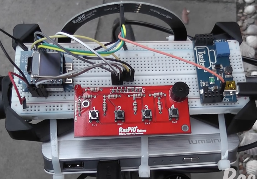
I grabbed one of my prototype button boards (which never made it to market, but are darned useful nevertheless) and wired it up to another Wemos. I also put a little OLED screen on there so we could display which button had been pressed. This was as a result of not knowing ‘current status’ when using the phone interface. It was there as a kind of debug output.
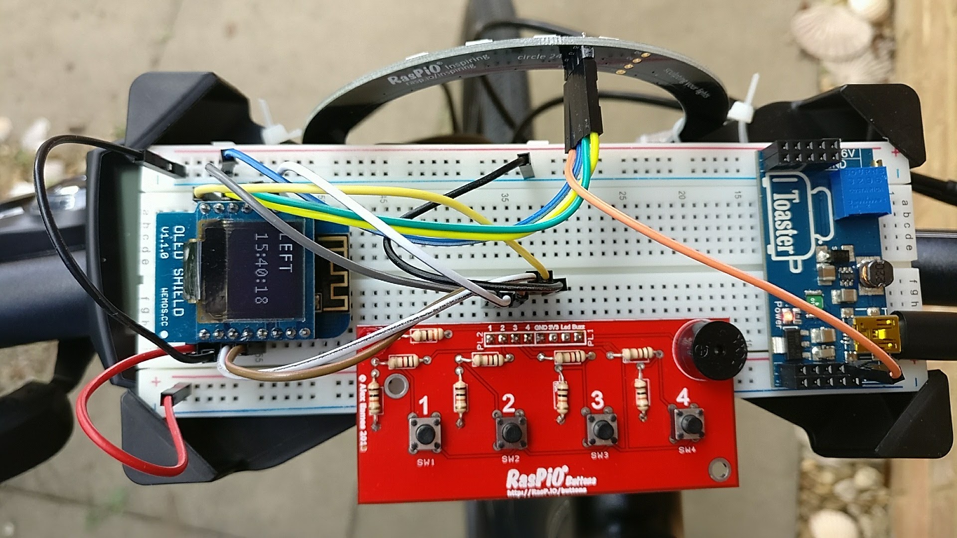
Day 2 front setup. Wemos, OLED, Button board, Toaster and large breadboard
I also wired up a RasPiO InsPiRing Circle as the front light. I had the idea that, most of the time, it could act as headlight at ~50% white brightness (switchable to 100%). But, when signalling right or left, we could use a yellow animation much like on the back, using half of the circle to display the direction indicator, like this…
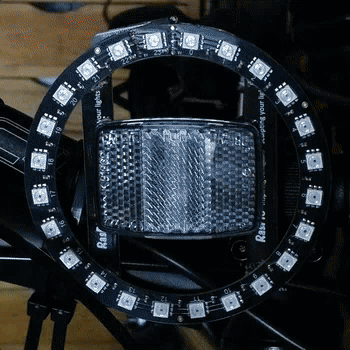
Front indicator turning left
Programming all of this took a little while. Fortunately I had some previous ‘sketches’ that enabled me to control the OLED and RasPiO InsPiRing LEDs. So it was mostly about creating the program flow control, getting the animations correct and implementing button press detection.
Comms – Front-to-back
The other thing was that, now we have two devices, we have to get them to talk to each other. I persisted with the phone WiFi HotSpot for now. Eliminating that was to be a task for day 3 (I ended up using a Pi Zero W, but that’s tomorrow’s story). But for now, both Wemos signed into my phone, which happily gave them consistent ip addresses. This enabled me to hard code the rear Wemos‘ ip address into the front Wemos‘ sketch, so it could send the appropriate ‘GET’ calls to the rear Wemos web server.
Having a screen and WiFi access point with internet, I decided to run an NTP clock on the Wemos as well “because we can”. The code for that was ripped from one of my other sketches. I initially had the clock running on the RasPiO InsPiRing ring as well, but I quickly binned it as a bit ‘naff’, preferring to have white front lights.
You’re Not Putting a Breadboard on Your Bike?
After making some video of day 1’s progress, I realised that my full-sized breadboard would mount perfectly in my bike’s mobile phone holder. So, with the help of cable ties, I secured both breadboard and InsPiRing circle to the front of my bike. I agree it looks ridiculous, but it’s only temporary and nobody who saw it actually laughed!
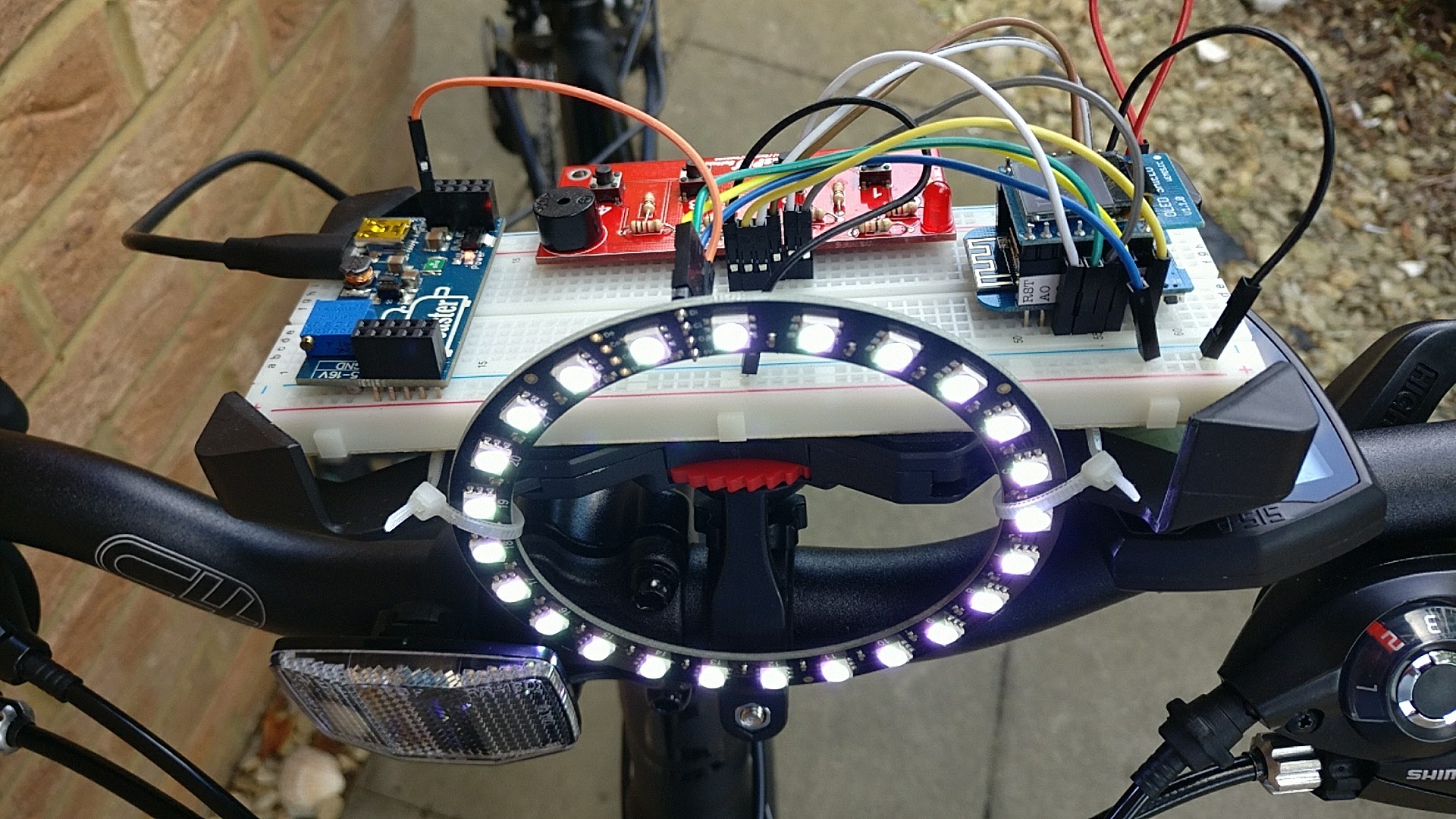
You CAN mount a full-size breadboard on your bike!
A way-bigger-than-needed 10000 mAh Lumsing USB battery pack was slung under this with large cable ties. I used my ‘toaster’ breadboard power supply between them.
Unnecessarily large battery pack, but it’s what I had at the time
The phone (hotspot) went in the saddlebag along with the battery for the rear lights.
Road Test Time + Video
At this point, having done all the bench testing and getting everything working as I wanted, it was time for another road test. I wanted to test in the evening so I could get some video. Videoing LEDs is hellish difficult, but it works a little better in dim light. The hard part is not over-exposing them and ‘blowing out’ the colours. For example, the indicator/turn signal LEDs are rather yellow, but can look a bit washed out on film. Here’s the full day 2 video…
An Excellent Idea from my Neighbour
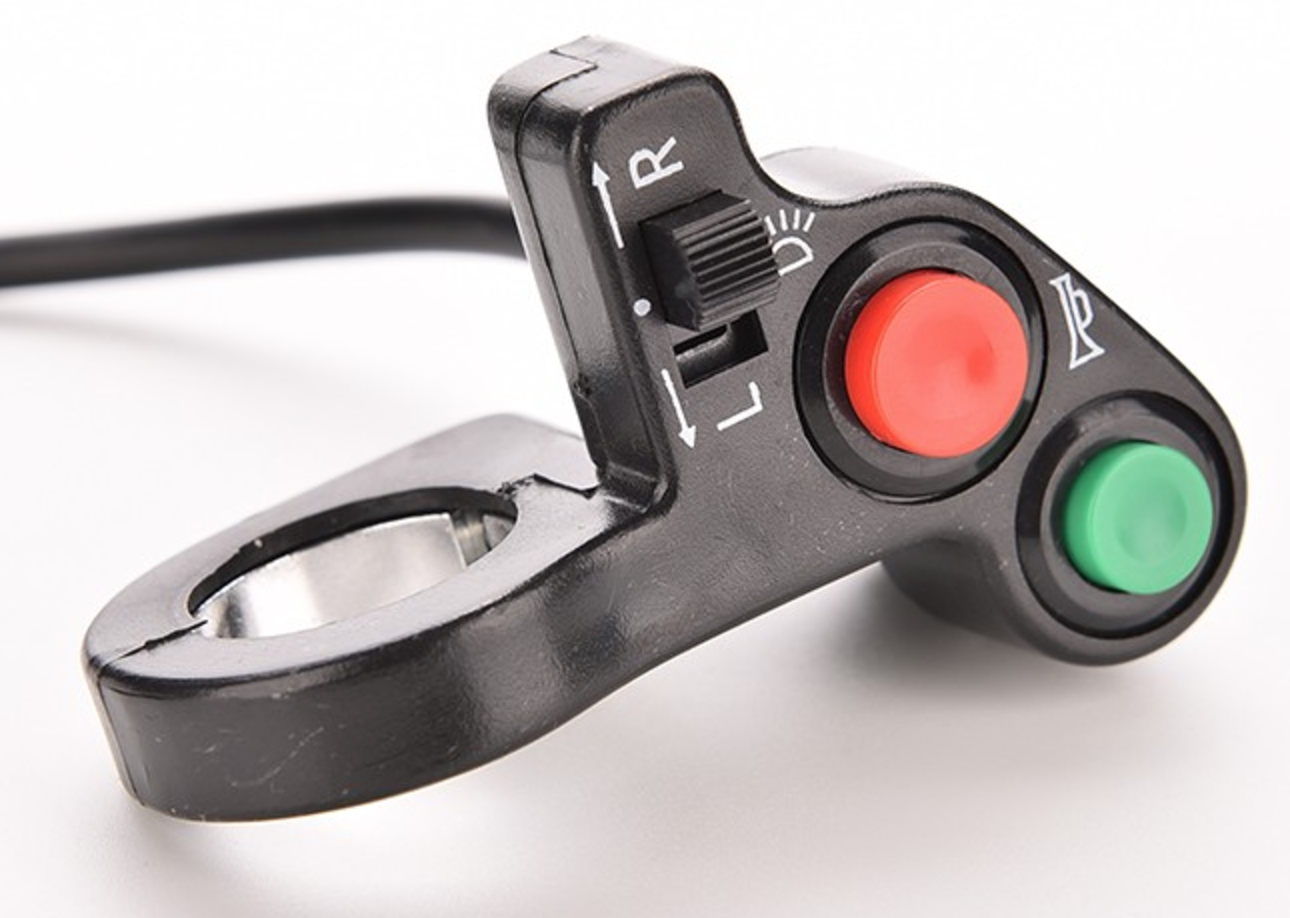
After talking to Terry, I ordered this moped switch
While I was outside filming, my neighbour Terry came outside and was amazed. In fact, everyone who has talked to me about the lights has said they are excellent. I showed Terry how it all worked and he said “You know? On a motorbike you have a little switch that you push left/right and cancel it when you’ve made your turn. Maybe you could have something like that?” I thought that was an excellent idea, so I went off to ebay/Farnell/RS web sites in search of exactly such a thing. I’d been wondering what sort of switch to use and eventually decided to buy something specifically made for a moped/quad.
The road testing went very well and I carried on using this system for a couple of days every time I went out on my bike. In the meantime I worked in parallel on some of the issues below…
Problems Encountered & Annoyances
1) Timings & no Threading
The main issue I found unsatisfactory was that, when using two Wemos D1 mini and an http GET, the controlling front Wemos will wait and be unable to do anything until it gets a ‘200’ response or a timeout from the rear (web server) Wemos.
I’m using Arduino coding to drive these. Since there is no threading in Arduino (as far as I can tell, anyway) I was unable to solve this problem. I came up with a workaround, which was to alternate the indicators (as you can see in the day 2 video), but it wasn’t quite as nice as I wanted. Real vehicles have indicators that flash simultaneously. WE CAN DO THAT!
2) Failed Button Presses
One of the buttons – the one I was using for the BRAKE function – kept failing. The hardware was fine. I tested it. I even tried changing ports on the Wemos, swapping wires round, using different buttons. Perhaps it was something in my polling code? (I expect it was.) I don’t know, but the BRAKE function seemed to fail randomly. This was annoying!
3) It Uses 3 Devices
The other thing that ‘bothered me’ about my initial setup was that it uses three devices (two Wemos and a phone). This is ridiculous. One of them must go! Clearly 2 devices should be enough for this application. I don’t want to have to use my phone to ‘hotspot’ my bike lights. OK it was great for a quick test, but it’s not a long-term solution.
So on day 3, I spent some time addressing the above 3 issues, but I’ll tell you all about that in the next post. I hope you’re enjoying the series. If you want to make your own, I have set up a BIKE bundle on the RasPiO InsPiRing page.
Nice idea:)
A small suggestion…you can dimming the light of the half static part while turning left/right.
This is how Audi does for front lights.
Good idea. I might look at that :)
HTTP uses TCP, which as you’ve noted requires each packet to be ACKnowledged before proceeding. In your example, I wonder if you might be better using a UDP connection instead? You get no confirmation that the packet has been received, but then you don’t need to wait for a reply either…
Alternatively, would it be possible to also run the rear lights from the front Wemos? Or would wires of that length be too ugly and/or pick up too much interference?
That sounds like it would work if the Wemos libraries support UDP (I suspect they probably do).
It should be possible to run it all from one device if wires were acceptable, but I’m not sure how well the rear lights would perform with a long run of wire carrying the SPI signals. However, “no wires front-to-back” was pretty much my one main unbreakable directive for this project.
Really excellent project series. :-) Looking forward to seeing how you solved the hotspot problem and other issues!
Thanks Mike.
Haha – in real life I’ve pretty much completed day 5 and into “ideas for further development”. But as you know blogging and videos take a very long time. Actually it seems to take as long to make the video and write the blog as it does to “do the thing”. Imagine how long it would take if I was really fussy about producing slick videos? (Unthinkably long). Day 3 is pretty much written and video done though, so it should be out some time next week :)
I’ve taken the whole setup off my bike now and installed it on a portable mock-up handlebar so I can show it at the Hackaday Unconference tomorrow.