
I wanted to check out the GPIO ports on the Raspberry Pi B+. The new B+ has 26 ports available for GPIO work. The previous model B had 17 on the main (P1) header and four more on the now deleted P5 header. The top 26 pins are all the same, but the 14 new pins contain 9 GPIO ports. There’s a full explanation of the ports in the diagram here…
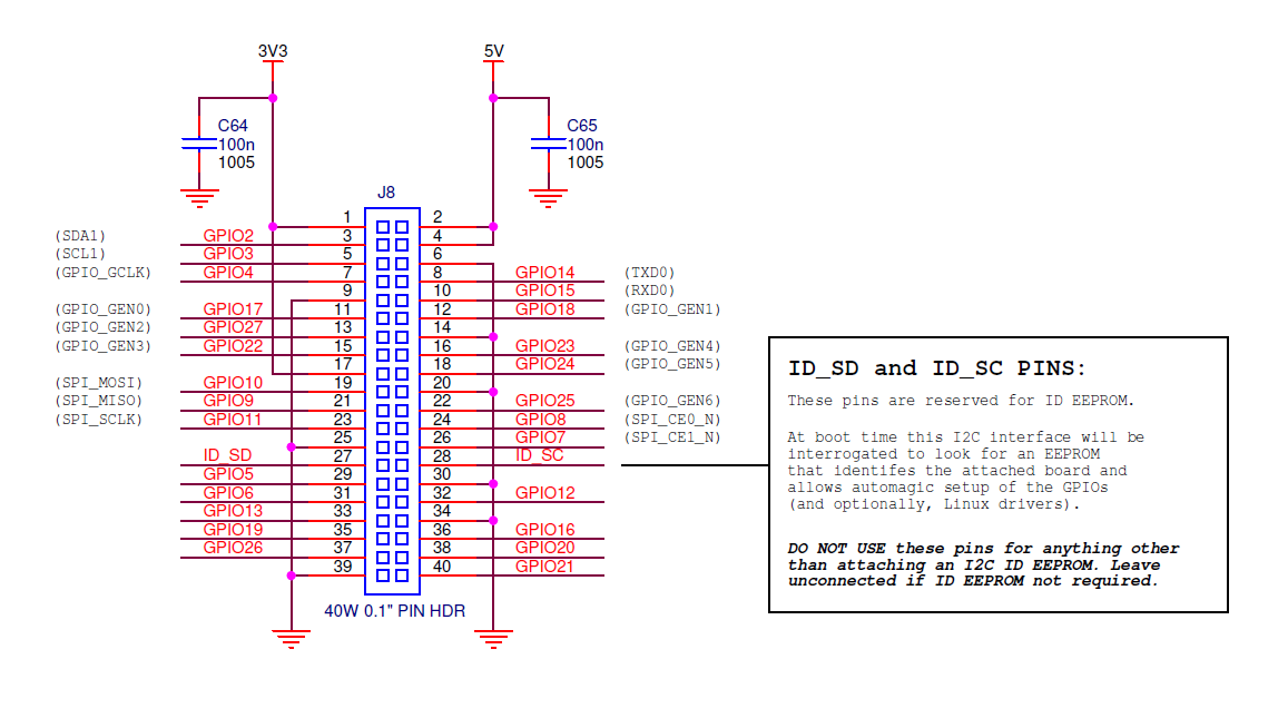
Raspberry Pi B+ GPIO pinouts (click to enlarge)
How to Test All 26 ports?
Why with LEDs of course. You can do it by connecting an LED and resistor (~330 Ohms is a nice safe value) to each port. But for the sake of the video, that would be a bit messy. So I used some surface mount LED boards I made last year.
Check out the video…
Here’s The Code
If you want to have a go yourself, here’s the code I used. It’s a bit rough and ready, but it works, and I’ve put some comments in. You don’t have to create a backwards copy of the list, you can iterate through it backwards, but I’ve demonstrated both techniques here in this program, just for fun. And who knows, someone out there might learn a new trick?
import RPi.GPIO as GPIO
from time import sleep
GPIO.setmode(GPIO.BCM)

leds = [2,3,4,17,27,22,10,9,11,5,6,13,19,26,14,15,18,23,24,25,8,7,12,16,20,21]
leds1 = [2,3,4,17,27,22,10,9]
leds2 = [11,5,6,13,19,26,14,15]
leds3 = [18,23,24,25,8,7,12,16]
leds4 = [20,21,24,25,8,7,12,16] # had to cheat a bit here as only 2 leds on board 4
leds_back = leds[:]             # make copy of leds list so we can reverse it
leds_back.reverse()             # reverse it

for i in leds:                         # loop through leds flashing each for 0.1s
    GPIO.setup(i, GPIO.OUT, initial=0) # sets i to output and 0V, off
    GPIO.output(i, 1)    # sets port on
    sleep(0.1)
    GPIO.output(i, 0)    # sets port off

for i in leds_back:      # loop through them all in reverse
    GPIO.output(i, 1)    # sets port on
    sleep(0.1)
    GPIO.output(i, 0)    # sets port off

try:
    x = 0
    while x < 100:
        x += 1
        # now we take each group of 8 and switch them all at the same time
        # forwards
        for i in range(8):
            GPIO.output(leds1[i], 1) # sets port on
            GPIO.output(leds2[i], 1) # sets port on
            GPIO.output(leds3[i], 1) # sets port on
            GPIO.output(leds4[i], 1) # sets port on
            sleep(0.1/x)
            GPIO.output(leds1[i], 0) # sets port off
            GPIO.output(leds2[i], 0) # sets port off
            GPIO.output(leds3[i], 0) # sets port off
            GPIO.output(leds4[i], 0) # sets port off
        # then backwards
        for i in range(7,-1,-1):
            GPIO.output(leds1[i], 1) # sets port on
            GPIO.output(leds2[i], 1) # sets port on
            GPIO.output(leds3[i], 1) # sets port on
            GPIO.output(leds4[i], 1) # sets port on
            sleep(0.1/x)
            GPIO.output(leds1[i], 0) # sets port off
            GPIO.output(leds2[i], 0) # sets port off
            GPIO.output(leds3[i], 0) # sets port off
            GPIO.output(leds4[i], 0) # sets port off
finally:
    GPIO.cleanup() # clean up the ports on exit, no matter why it exits
Do we know what the specialised functions of the new GPIO pins are? I heard some of them provide additional hardware clocks.
BTW, I tested the Guzunty CPLD peripheral for compatibility with the B+. It works fine :-)
They’re all in the BCM2835 data sheet.
I know. I was just too lazy to go look them up if you knew already :)
There are no default ones. And most of them have multiples. E.g. there’s another spi bus with 3 chip select ports, which means you could theoretically add ~800 ports to the Pi with port expanders.
Nice. Now we just need that support added to the Raspbian SPI driver… :)
Go on. It’s all there on pages 102/103 of the data sheet http://www.raspberrypi.org/wp-content/uploads/2012/02/BCM2835-ARM-Peripherals.pdf
I’d love to. Unfortunately, there is the day job to think about :)
How tiresome :(
I couldn’t resist it and looked at the data sheet. :O There are also a couple of PWM signals on GPIOs 12 and 13. That’s a new capability for the Pi.
I think you can only use two channels at once on the BCM though (ISTR it only has 2) and one is used for analog sound.
Yup, only two PWM channels on the BCM2835 – http://elinux.org/RPi_BCM2835_GPIOs
By default one is used for left analogue audio out and the other is used for right analogue audio out. But if you’re not using analogue audio, you can use them for your own purposes (I’ve never done this myself though). On the Model B only one PWM was available on the P1 GPIO header, but on the B+ they’re both available on the J8 GPIO header.
“And who knows, someone out there might learn a new trick?”
An easier way to get a reversed copy of a list is:
leds_back = leds[::-1]
And you could create the individual ledsN lists using array-slicing:
leds = [2,3,4,17,27,22,10,9,11,5,6,13,19,26,14,15,18,23,24,25,8,7,12,16,20,21]
leds1 = leds[0:8]
leds2 = leds[8:16]
etc. (obviously that wouldn’t work for leds4 though!)
Great tips. Thanks Andrew. I knew about slicing, but didn’t think of using it for that.
The [::-1] is a completely new one to me though :)
I have a quick question. I’m able to get my GPIO on my pi B+ working however to turn voltage on, i must set the pin output to 0 and off is 1. Any idea why this would be reversed on mine?
Not really without seeing both your wiring and your code. A wild guess could be that your GND wire is on the wrong pin?
hmm. All I’m doing is running outputs to resistors to LED’s to ground. Everything works perfectly except the logic is reversed. There’s nothing more to the circuit. I’m certain that ground is on the correct pin. I have a B+ cobbler and I’ve discovered that all of the outputs are opposite what they are labeled (as if the ribbon cable is backwards) however there’s only one way the ribbon cable can be oriented. I’m wondering if i received the wrong cable.
What about ID_SC and ID_SD – these are in reality GPIO 0 & 1. After the boot up they should be usable as just GPIO pins. As long as nothing is connected to them that holds the pin low during boot up it should be fine. Have you testes this?
No I didn’t because they’re reserved for the ID EEPROM of a HAT. Not something your average hacker would want or need. We were discouraged from using those ports for anything else.