Multiple threaded callback interrupts in Python
We’ve been learning about interrupts this week because of the brand new interrupt capabilities of RPi.GPIO. We covered a simple “wait for” interrupt in part 1, threaded callback interrupt and button debouncing in part 2 and today we’re getting sophisticated with multiple threaded callbacks. “WoooooooooOOOOOOOOOOOOOOOooooooooooo”, I hear you say. ;)
Well actually, we’re not doing much that’s very different from last time, except, now there’s more of it. We’ll add another button and another threaded callback function the same as the first one (but on a different GPIO port). This is just to show that you can do multiple threaded callbacks in one program. After that, your imagination is the limit. (Well actually the number of GPIO ports is probably the limit.)
We’re just building on what we did before and this is exactly how programs are made. You do a bit at a time, test it, fix it, make sure it does what it ought to do, then go on to the next bit.
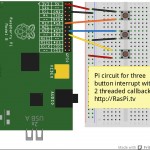
Here’s the Circuit
This circuit is a bit different from the previous one. The top two buttons connect port 17 and port 23 to GND when pressed. These are the two which trigger callbacks. The bottom button, connecting port 24 to 3V3 on button press is the “wait for” interrupt this time. So when you press button 3 it’s “game over”, but buttons 1 and 2 just report that they’ve been pressed until button 3 is eventually pressed.

Circuit for 2 threaded callbacks and one wait interrupt
We’ve used all the same building blocks we developed in parts 1 and 2, including button debouncing.
Do you need to update RPi.GPIO?
If you didn’t do it for the first or second examples, you will quite likely need to update your RPi.GPIO package. You can check what version of RPi.GPIO you have in the command line with…
sudo python

import RPi.GPIO as GPIO

GPIO.VERSION
This should show you what RPi.GPIO version you have. You need 0.5.1a or higher for this example.
You can exit the python environment with CTRL+D
Install RPi.GPIO version 0.5.2a for multiple threaded callback interrupts
If you need to, you can install 0.5.2a or later with
sudo apt-get update (This will update all your Raspbian packages and may take up to an hour)
sudo apt-get upgrade
Update July 2014
The best way to get the latest RPi.GPIO (currently 0.5.5) is to flash a new SD card with the latest NOOBS or Raspbian. This will give you a clean start with the latest version of RPi.GPIO.
And now onto the code
I’ve put most of the explanations in the code, so that if you use it, you will still have them.
#!/usr/bin/env python2.7
# script by Alex Eames https://raspi.tv
# https://raspi.tv/how-to-use-interrupts-with-python-on-the-raspberry-pi-and-rpi-gpio-part-3
import RPi.GPIO as GPIO
GPIO.setmode(GPIO.BCM)

# GPIO 23 & 17 set up as inputs, pulled up to avoid false detection.
# Both ports are wired to connect to GND on button press.
# So we'll be setting up falling edge detection for both
GPIO.setup(23, GPIO.IN, pull_up_down=GPIO.PUD_UP)
GPIO.setup(17, GPIO.IN, pull_up_down=GPIO.PUD_UP)

# GPIO 24 set up as an input, pulled down, connected to 3V3 on button press
GPIO.setup(24, GPIO.IN, pull_up_down=GPIO.PUD_DOWN)

# now we'll define two threaded callback functions
# these will run in another thread when our events are detected
def my_callback(channel):
    print "falling edge detected on 17"

def my_callback2(channel):
    print "falling edge detected on 23"

print "Make sure you have a button connected so that when pressed"
print "it will connect GPIO port 23 (pin 16) to GND (pin 6)\n"
print "You will also need a second button connected so that when pressed"
print "it will connect GPIO port 24 (pin 18) to 3V3 (pin 1)\n"
print "You will also need a third button connected so that when pressed"
print "it will connect GPIO port 17 (pin 11) to GND (pin 14)"
raw_input("Press Enter when ready\n>")

# when a falling edge is detected on port 17, regardless of whatever
# else is happening in the program, the function my_callback will be run
GPIO.add_event_detect(17, GPIO.FALLING, callback=my_callback, bouncetime=300)

# when a falling edge is detected on port 23, regardless of whatever
# else is happening in the program, the function my_callback2 will be run
# 'bouncetime=300' includes the bounce control written into interrupts2a.py
GPIO.add_event_detect(23, GPIO.FALLING, callback=my_callback2, bouncetime=300)

try:
    print "Waiting for rising edge on port 24"
    GPIO.wait_for_edge(24, GPIO.RISING)
    print "Rising edge detected on port 24. Here endeth the third lesson."

except KeyboardInterrupt:
    GPIO.cleanup()       # clean up GPIO on CTRL+C exit
GPIO.cleanup()           # clean up GPIO on normal exit
Bounce
bouncetime=300 in lines 34 & 39 sets a time of 300 milliseconds during which time a second button press will be ignored. The code from example 2a has been incorporated into RPi.GPIO.
You can download this directly to your Pi using…
wget https://raspi.tv/download/interrupt3.py.gz

gunzip interrupt3.py.gz
Then you can run it with…
sudo python interrupt3.py
Can I switch off an event detection?
There’s just one more thing. If you want to stop an event detection on a particular port, you can use the following command…
GPIO.remove_event_detect(port_number)
You now know all you need to know about how to create and manage interrupts in RPi.GPIO in Python on the Raspberry Pi. The official documentation is here if you want to check it out.
Have fun with interrupts. I hope this mini-series has been useful. Let us know, in the comments below, what you’re planning to use it for and then come back and tell us how it went. :)
For extra credit, can you tell me why I chose those specific GPIO ports for these experiments?
RasPiO® GPIO Reference Aids
Our sister site RasPiO has three really useful reference products for Raspberry Pi GPIO work...
[…] hope you are enjoying this series. Click here for Part 3. Share this: Posted by alex at 8:00 am Tagged with: interrupts in python with […]
Thank you so much!
I started fooling arround with the Raspberry Pi not long ago and that made me start learning Python. Your articles about interrupts were essencial.
I made a little Python script that lights up a Green LED when I get new mail and a RED one when the temperature forecast to my city gets lower than 5ºC. But the forecast site free API only gives a limited number of updates a day. Because of that the temperature as well as the email are updated every 3 minutes.
However, after reading this, I setted up a button that refreshes the e-mail status by pressing it using the callbacks.
The next step will be making this information avaliable in a 16×2 LCD. (following one more of your posts :-D )
Excellent :)
Alex, do you recommend me any book or website to begin learning Python. Beacuse sometimes I have some problems with the sintax of the code :x
Learn Python the Hard Way is really good for Python 2.x (in my opinion). Not only that, but it’s online and free. You can start right away. :)
People say good things about Dive into Python as well
This is a great tutorial; thanks for the example code as well. I am guessing that you have chosen the pins that you have due to them not having any special function, eg: UART, SPI etc.
Thanks John.
Ref the port choices, that’s part of it, but not the whole story. :)
Mind sharing the details regarding your pin choices then, or should I stay tuned for a future tutorial :)
As well, do we need to manually clear these interrupts under any circumstances, or is there a method to clear them that you are aware of? I ask because I am not sure if that may be my problem. I have written the attached code to allow an rotary incremental encoder (outputs 2 bit grey code changing with a change in angle) to control which stream in my mpd playlist is active, and the call backs are only triggered up until the if statement in the body of the while loop at the bottom is processed for the first time. If I cut the 2 If statements at the bottom and paste them into the call backs it works well. Any help would be greatly appreciated, I am still a bit green with Python and programming in general:
import RPi.GPIO as GPIO
import time
import os
GPIO.setmode(GPIO.BOARD)
GPIO.setwarnings(False)
GPIO.setup(18, GPIO.IN, pull_up_down=GPIO.PUD_DOWN)
GPIO.setup(16, GPIO.IN, pull_up_down=GPIO.PUD_DOWN)
GPIO.setup(7, GPIO.IN, pull_up_down=GPIO.PUD_DOWN)
counter = 5
lastcounter = 5
timestamp16 = time.time()
timestamp18 = time.time()
def callback16():
global timestamp16
global counter
global lastcounter
time_now = time.time()
if (time_now – timestamp16) >= 0.1:
current16 = GPIO.input(16)
current18 = GPIO.input(18)
if current16 == 0:
if current18 == 0:
counter = counter – 1
else:
counter = counter + 1
else:
if current18 == 0:
counter = counter + 1
else:
counter = counter – 1
print ‘callback 16’
timestamp16 = time_now
return
def callback18():
global timestamp18
global counter
global lastcounter
time_now = time.time()
if (time_now – timestamp18) >= 0.1:
current16 = GPIO.input(16)
current18 = GPIO.input(18)
if current18 == 0:
if current16 == 0:
counter = counter + 1
else:
counter = counter – 1
else:
if current16 == 0:
counter = counter – 1
else:
counter = counter + 1
print ‘callback 18’
timestamp18 = time_now
return
os.system(‘clear’)
os.system(‘mpc’)
GPIO.add_event_detect(16, GPIO.BOTH, callback=callback16)
GPIO.add_event_detect(18, GPIO.BOTH, callback=callback18)
while GPIO.input(7) == 0:
time.sleep(.1)
if counter > lastcounter + 4:
os.system(‘mpc next’)
os.system(‘clear’)
os.system(‘mpc’)
lastcounter = counter
if counter < lastcounter – 4:
os.system('mpc prev')
os.system('clear')
os.system('mpc')
lastcounter = counter
print str(GPIO.input(16)) + " " + str(GPIO.input(18))
GPIO.cleanup()
Pin choices answer can be found in the comments for part 2 of this series. I’ll leave it there so as not to act as a spoiler in case anyone wants to have a guess. :)
I’ll look at your code a little later as I have a headache right now. WordPress seems to have mangled it as well :(
Thanks for the offer to assist. I can upload the code somewhere if it’ll help you not have to rebuild the indentation.
You can zip it up and email it to me if you like. my_first_name @ mydomain ;) (a lot of email providers won’t pass .py files)
I probably won’t be able to look until Tue/Wed though as I’m travelling tomorrow. I just might have a few minutes tomorrow am if things go well, or I feel like it on the plane :)
Hi Alex, your description on how to use interrupts is very easy to understand. However I upgraded my gpio today to version 0.5.2a before I tried your lessons. Now lesson 2 and 3 have errors. When I change the sd card to one with version 0.5.1a it all works fine. My python skills are not that great yet, bit i’m learning. I had great fun getting a wii_mote controlling the robot used in the skutter project in the magpi.
Andrew
I’m afraid it’s a known bug. Ben wrote to me about this at the weekend. 0.5.2a (a stands for alpha) has changed such that the callback functions will require channel number. Just add the channel number in your callback function definition and all should be good. I am going to fix the example code as soon as 0.5.2a goes into the Raspbian repo. So if you define a function for channel 25 it should look like this…
def callback_25(25):I haven’t changed it yet because it will break the example for the previous versions.
Thanks Alex, I tried it but I keep getting an invalid syntax error on the (25): . I also tried the bouncetime function but can’t get past def callback_17(17):
Andrew
I haven’t even had a chance to play with this version yet, so you’re ahead of me ;)
In other news wiringpi2 for python just failed to install as well. I think I’m going to do something that actually works now. :-D
I’ve gone back to 0.5.1a now and wait until it’s in the repo.
It’s an awkward one because I will need to change the code, but don’t want to do it until the new version is the default (in the repo).
Try putting “self” instead of the channel number such as:
def my_callback(self):
This worked for me.
Yes using self instead of the channel number works for me too.
I wonder if this is going to change in the near future? ?:-)
I also notice that version 0.5.2a is now in the Raspbian repo. :yes:
Updated both this page and the previous examples and downloads to reflect the changes in RPi.GPIO from version 0.5.2a
Basically you HAVE to include (channel) in your callback function definitions. Not channel number, but the variable called channel
I didn’t want to do it until 0.5.2a was in the repo as it breaks the examples for previous version 0.5.1a.
If you try to run the code from the old example (or the one in part 2) using 0.5.2, you will get this error when your callback function is called…
TypeError: my_callback() takes no arguments (1 given)Thanks Alex, I’m pleased to note that your new code is almost the same as what I did. I say almost as I have found that almost anything can be inserted between the () so long as it starts with a letter. You could use (raspberry) or even (raspi_tv) if you want and the two callbacks can even have different variables between the ().
That’s interesting, so any variable starting with a letter will do. :)
Ben flagged up the changes to me about 10 days ago, but it seemed sensible to hold off updating until 0.5.2a was the “official” version. Didn’t want to get too many people stuck between versions, and didn’t want to have several different versions of these pages.
Alex I understand your dilemma, but this must be a bug and I’m sure that Ben will change it in the next release. Then you’ll have to change it again :silly:
We’ll see. Hopefully the code won’t be broken again. :-)
[…] is the third part of a series sharing about “interrupts” on the Raspberry Pi, from RasPi.TV: We’ve been learning about interrupts this week because of the brand new interrupt […]
You chose GPIO18, GPIO23 and GPIO24 because of internal pull-up resistors. Am I right?
Good guess, but it’s not the whole story. :) It’s more to do with what’s next to each of those pins :)
They have interrupt vectors assigned at hardware level? I dare assume that not all pins have this capability.
They might do, but I wouldn’t have an idea. It’s simpler than that. ;)
Because those pins are not used by any of peripherals like UART, I2C, ADC? Or simply they are closer to the breadboard? :D
All good reasons, but not THE one. Big clue now. Look at the pins adjacent to the chosen ones and see if they have any useful properties. ;)
They have ground pins beside them, and therefore, if are configured to have internal pull-up resistors they can be connected to switches wired to simple 2 pin female connectors. ie: a switch (or button) between pin 9 and 11, one between 14 and 16, as well as 18 and 20.
There are those mysterious DNC pins (Do Not Connect). There must be some reason not to bother with them. May be some future functionality? Or may be my pinout chart is out of date already?
Two grounds and a 3V3 – just what we needed for this. The rest of it is as John says above. :) I didn’t use a breadboard for this, I used button switches connected to 2-way female connectors. Unfortunately the Fritzing Pi model won’t allow connections to the DNCs.
Has anyone done any speed testing on this? I’ve been trying to work out whether I could turn a RPi into an ECU for my rather old car (bonkers I know). The stumbling block has been how to measure engine revs reasonably accurately.
Getting one pulse per rev is pretty easy. Trigger an interrupt each time and log the timestamp. Subtract last timestamp from this timestamp and we have the time taken for 1 revolution but at 5000 RPM the pulses are arriving at 12 millisecond intervals.
Am I being completely stupid or could Python on the Pi be fast enough?
Thoughts?
It might be fast enough, but I doubt if Python would give you accurate enough timings for such a critical app. I think you’d be better off with a real-time microprocessor like ATMega or something else like it.
I made something similar for jet engines about 20 years ago. Put a 6522 Rockwell VIA in the way.. it does the counting.
Great tutorial! I wasn’t particularly fond of polling, so this was a handy find.
I notice that you can call one function for both rising and falling edges using GPIO.BOTH, and you can call more than function using GPIO.add_event_callback, but can you call one function for rising and a different function for falling?
When I try to do this I get an exception:
RPi.GPIO.AddEventException: Edge detection already enabled for this GPIO channel.
Is there a reason why this isn’t allowed?
You can do it on different channels. Surely there’s a workaround though? Do ‘both’ and the test for high or low in your callback function to determine what happens?
Failing that, Ben’s the man to answer.
I had the same problem. I wanted to use this with two door sensors to detect if a chicken coop door is fully closed, fully open, or somewhere in between. For each sensor, I’d be able to tell if the door was arriving at that location or departing that location by the rising or falling edge.
I tried your workaround… trigger the function on GPIO.BOTH and then do an if/else test in the callback function to see if the door was at that location (if it was, it had just arrived, if it was not, it had just left).
Works great. Thanks for the tip! And thanks for the tutorials… I would not have gotten this working otherwise.
Thank you for your great tutorial. it helped me alot for my little project.
You’re very welcome. That’s what this blog is here for. It’s nice to know it helps people. :)
While the comments correctly indicate that port 24 is connected to 3v3, the diagram seems to indicate a connection to 5V. I don’t want anyone to smoke their RPi by mistake.
It doesn’t, but I can see how you could think that it did if you were using a small screen or something. I’ve found out how to “bend” wires in Fritzing now, so will try to avoid passing directly over ports in future.
Someone just reported destroying a Pi while following your tutorial: https://www.reddit.com/r/raspberry_pi/comments/9lpmwf/help_did_i_short_something/ I suggest you change the pic.
There’s nothing wrong with the picture. The person in the Reddit post admitted “i may have been off by a pin’.
User error. No need to change the pic.
My RPi.GPIO package was not up to date so I followed your upgrade steps but every time I output my version it’s the old one. All updates run like they should without any errors. And in the logs it even shows the upgraded version.
Preparing to replace python-rpi.gpio 0.5.2a-1 (using python-rpi.gpio_0.5.2a-1_mhf.deb) ...

Unpacking replacement python-rpi.gpio ...

Setting up python-rpi.gpio (0.5.2a-1) ...
>>> import RPi.GPIO as GPIO

>>> GPIO.VERSION

'0.4.1a'
Any idea what I’m missing or doing wrong?
It’s possible that if you’ve installed previous version of RPi.GPIO manually in the past, you might need to uninstall those before the newer version will “take”. Ben knows more about how to do this and is usually pretty quick to suggest how to test/do this in the Python section of the Pi forums.
In your example about how to check the RPi.GPIO version, you show exiting with a ^Z.
That puts the python task into the backround, without stopping it.
root@mypi3:~/bin# python
Python 2.7.3 (default, Jan 13 2013, 11:20:46)
[GCC 4.6.3] on linux2
Type “help”, “copyright”, “credits” or “license” for more information.
>>> import RPi.GPIO as GPIO
>>> GPIO.VERSION
‘0.5.3a’
>>> (typed a ^Z)
[1]+ Stopped python
Checking the backround jobs:
root@mypi3:~/bin# bg
[1]+ python &
Bringing python back to the foreground:
root@mypi3:~/bin# fg 1
python
>>>
Really exit and stop python
>>> exit()
This will avoid having extra python jobs running in the backround.
Actually someone already mentioned this a while back (may have been on another page) and said that CTRL-D is better (EOF).
Thanks for bringing it up. I’ll change it.
Hi,
thank you for your great tutorial. it helped me a lot.
I am trying to create a project for a museum: pi to stream video to a screen.
We must select a movie from a console with 8 pushbuttons.
The console is connected to the GPIO port 4 and 18 for testing, but my script does not quite work.
os is “RASPBIAN”, so the versions are:
python: 2.7.3
RPi.GPIO: 0.5.2a
the script:
————————————————————————————-
#!/usr/bin/env python2.7
import RPi.GPIO as GPIO
import os
from time import sleep
def ports_def():
GPIO.setmode(GPIO.BCM)
GPIO.setup(4, GPIO.IN) # button 1
GPIO.setup(18, GPIO.IN) # button 5
GPIO.setup(4, GPIO.IN, pull_up_down=GPIO.PUD_UP) # button 1
GPIO.setup(18, GPIO.IN, pull_up_down=GPIO.PUD_UP) # button 5
GPIO.add_event_detect(4, GPIO.FALLING, callback=my_callback1, bouncetime=300)
GPIO.add_event_detect(18, GPIO.FALLING, callback=my_callback2, bouncetime=300)
def my_callback1(channel):
os.system(“pkill omxplayer”)
os.system(‘omxplayer ../videos/50001_court.mp4’)
def my_callback2(channel):
os.system(“pkill omxplayer”)
os.system(‘omxplayer ../videos/coin_court.mp4’)
def balise1():
while 1:
print “la forge”
sleep(0.02);
ports_def()
balise1()
GPIO.cleanup()
————————————————————————————–
the problem is the following:
video process can sometimes exist in duplicate:
root 1890 1 0 05:51 tty1 00:00:00 /bin/login —
pi 1975 1890 0 05:53 tty1 00:00:01 -bash
root 1989 1975 0 05:53 tty1 00:00:00 sudo ./test.py
root 1990 1989 94 05:53 tty1 00:03:34 python2.7 ./test.py
root 2141 1 15 05:57 tty1 00:00:00 /usr/bin/omxplayer.bin ../videos/coin_court.mp4
root 2142 1990 0 05:57 tty1 00:00:00 sh -c omxplayer ../videos/coin_court.mp4
root 2143 2142 0 05:57 tty1 00:00:00 /bin/bash /usr/bin/omxplayer ../videos/coin_court.mp4
root 2144 2143 15 05:57 tty1 00:00:00 /usr/bin/omxplayer.bin ../videos/coin_court.mp4
pi 2160 2003 0 05:57 tty2 00:00:00 grep –color=auto tty1
and after a while it can happen that you press a button does not detect…
Thanks for your help.
Maybe a brief sleep() between killing omxplayer and starting the next instance may help things?
Have you tried updating to the lastest RPi.GPIO ? (simply “sudo apt-get update && sudo apt-get upgrade”)
Have you tried experimenting with different bouncetimes?
Putting in some debug prints (i.e. each time you enter one of the callback functions) might be useful ;)
Presumably you’ve got the buttons wired to ground?
Thank you for your reply.
The buttons are wired to ground.
I’ll test your ideas and give you the results.
This other script works very well, but does not allow interruptions:
———————————————————————————-
#!/usr/bin/env python2.7
import RPi.GPIO as GPIO
import os
from time import sleep
# Ce programme est la propriete de l association La Forge
def ports_def():
GPIO.setmode(GPIO.BCM)
GPIO.setup(4, GPIO.IN) # button 1
GPIO.setup(18, GPIO.IN) # button 5
def balise1():
os.system(‘setterm -blank force’)
while True:
if ( GPIO.input(4) == False ):
os.system(‘omxplayer ../videos/50001_court.mp4’)
if ( GPIO.input(18) == False ):
os.system(‘omxplayer ../videos/coin_court.mp4’)
sleep(0.4);
ports_def()
balise1()
GPIO.cleanup()
———————————————————————————————
:-)
It’s almost certainly a debounce issue then (or a bug if you have an earlier RPi.GPIO). Trying Andrew’s suggestions is the best way forward :)
I made several tests:
I inserted a brief sleep() between killing omxplayer and starting the next instance, it was a little better, processes were not always two copies.
I experienced different bouncetimes, without success.
I would like to update the unit RPi.GPIO as you both recommend. The problem is that the Raspberry PI I use is the Model A, without ethernet jack for access to the Internet. So i can’t type “sudo apt-get update…”
Pull the SD card and do it with a model B?
Use a wifi dongle?
The other option is to download the .deb file manually http://code.google.com/p/raspberry-gpio-python/downloads/list and then use e.g. a USB flash drive (as the ModelA only has one USB port you’d obviously need to use a USB hub too!) to copy the file to the Pi https://raspi.tv/2012/mount-a-usb-flash-drive-on-raspberry-pi and then install it offline e.g. https://www.linuxquestions.org/questions/linux-software-2/installing-deb-package-offline-319519/
Yeah – I’ve found “setting up a model A for Wifi with no hub” an interesting experience – LOL. Much easier to do it on a B and swap cards.
thank you for your help, I’ll try as soon as possible. Cordially. CM
I’ve connected the INTA pin of a MCP23017 to the GPIO 23 via a 3.33V voltage divider to be able to use the interrupts generated by the MCP23017. However, the software debounce parameter doesn’t seem to work for me. When i include bouncetime=300 in the GPIO.add_event_detect the callback fires just once and then never again. any ideas why? Also, is there a workaround? Right now I do a sleep(0.3) in the callback, but I’d really like to go without any sleeps in my code…
thanks,
Tom
I think there was a bug in the bouncetime part of the code at one point. Are you using the latest RPi.GPIO? Of course you can always use your own debounce code as well (which you are, really).
I’m using RPi.GPIO-0.5.3a from the official repo (raspbian, apt-get install python-rpi.gpio). weird. anyway, I’m not much of a python programmer, but if using sleeps is ok so be it :)
In part 2 of this series I show you how to debounce without using sleep.
https://raspi.tv/2013/how-to-use-interrupts-with-python-on-the-raspberry-pi-and-rpi-gpio-part-2
It works by checking the time between what the computer sees as multiple button presses and ignoring the “second” press if sooner than a specified period of time.
hello,
I could load the package on a linux ubuntu pc and tranfer it to the sd card PI, the version is: RPi.GPIO > v 0.5.3a.
The installation “dpkg -i package-name” was easy on PI.
After many tests, no changes to the 0.5.2a version of … there are the same problems.
I saw that there was a dedicated package in real time: http://pythonhosted.org/RPIO/index.html
i’ll try and inform you of the results.
Here is the latest version of the program based on RPIO. After much testing, rather it seems to work. 8 GPIO inputs are each connected to a push button. At rest, the polarity is +3.3 v PI through resistance 10Kohms. When pushing the pin is grounded.
#!/usr/bin/env python2.7
# Association la forge Saint Martin La Plaine
# station video basee sur PI Raspberry type A
# Choix video sur pupitre equipe de 8 boutons poussoir
import RPIO
import os
from time import sleep
def ports_def():
RPIO.cleanup()
sleep(0.1);
RPIO.setmode(RPIO.BCM)
RPIO.setup(4, RPIO.IN)
RPIO.setup(17, RPIO.IN)
RPIO.setup(7, RPIO.IN)
RPIO.setup(22, RPIO.IN)
RPIO.setup(18, RPIO.IN)
RPIO.setup(23, RPIO.IN)
RPIO.setup(24, RPIO.IN)
RPIO.setup(25, RPIO.IN)
sleep(0.1);
RPIO.add_interrupt_callback(4, my_callback1, edge=’falling’, debounce_timeout_ms=800)
RPIO.add_interrupt_callback(17, my_callback2, edge=’falling’, debounce_timeout_ms=800)
RPIO.add_interrupt_callback(7, my_callback3, edge=’falling’, debounce_timeout_ms=800)
RPIO.add_interrupt_callback(22, my_callback4, edge=’falling’, debounce_timeout_ms=800)
RPIO.add_interrupt_callback(18, my_callback5, edge=’falling’, debounce_timeout_ms=800)
RPIO.add_interrupt_callback(23, my_callback6, edge=’falling’, debounce_timeout_ms=800)
RPIO.add_interrupt_callback(24, my_callback7, edge=’falling’, debounce_timeout_ms=800)
RPIO.add_interrupt_callback(25, my_callback8, edge=’falling’, debounce_timeout_ms=800)
sleep(0.1);
RPIO.wait_for_interrupts(threaded=True)
def my_callback1(gpio_id, val):
# fonction appel film1 bouton 1
ports_def()
sleep(0.1);
os.system(“pkill omxplayer”)
sleep(0.1);
os.system(‘omxplayer ../videos/film1.mp4’)
def my_callback2(gpio_id, val):
# fonction appel film2 bouton 2
ports_def()
sleep(0.1);
os.system(“pkill omxplayer”)
sleep(0.1);
os.system(‘omxplayer ../videos/film2.mp4’)
def my_callback3(gpio_id, val):
# fonction appel film3
ports_def()
sleep(0.1);
os.system(“pkill omxplayer”)
sleep(0.1);
os.system(‘omxplayer ../videos/film3.mp4’)
def my_callback4(gpio_id, val):
# fonction appel film4
ports_def()
sleep(0.1);
os.system(“pkill omxplayer”)
sleep(0.1);
os.system(‘omxplayer ../videos/film4.mp4’)
def my_callback5(gpio_id, val):
# fonction appel film5
ports_def()
sleep(0.1);
os.system(“pkill omxplayer”)
sleep(0.1);
os.system(‘omxplayer ../videos/film5.mp4’)
def my_callback6(gpio_id, val):
# fonction appel film6
ports_def()
sleep(0.1);
os.system(“pkill omxplayer”)
sleep(0.1);
os.system(‘omxplayer ../videos/film6.mp4’)
def my_callback7(gpio_id, val):
# fonction appel film7
ports_def()
sleep(0.1);
os.system(“pkill omxplayer”)
sleep(0.1);
os.system(‘omxplayer ../videos/film7.mp4’)
def my_callback8(gpio_id, val):
# fonction appel film8
ports_def()
sleep(0.1);
os.system(“pkill omxplayer”)
sleep(0.1);
os.system(‘omxplayer ../videos/film8.mp4′)
def main():
while 1:
# print “la forge”
sleep(3);
processname =’omxplayer’
tmp = os.popen(“ps -Af”).read()
proccount = tmp.count(processname)
if proccount == 0:
os.system(‘omxplayer ../videos/boucle.mp4’)
sleep(0.2);
ports_def()
sleep(0.1);
ports_def()
sleep(0.1);
main()
RPIO.cleanup()
Thanks to Alex and AndrewS…
thank you for the example
I have a question, is this is a SW or a HW interrupt ? I mean is the code checking for the button to be pushed ?
I’d say it’s a software interrupt that’s triggered, in this case, by hardware (i.e. the button press) but you can use them for anything you like, doesn’t have to be buttons.
Looks like it’s epoll_wait that actually handles the interrupts
http://code.google.com/p/raspberry-gpio-python/source/browse/source/event_gpio.c#355
i.e. AFAICT (this isn’t my area of expertise) the user-side code doesn’t do anything, until the kernel-side code kicks it back into life again.
Dear Alex
Many thanks for your excellent tutorials. It is generous of you to devote so much time to helping others.
I have been following your interrupt tutorials to help me detect rainfall using a tilting bucket rain gauge, and can print a message to screen saying “rain event detected”. I am however, unable, to return a value to accumulate total rainfall. I am sure that this is a very naive question, as I have yet to really get to grips with Python, but any help would be much appreciated.
Best wishes
Harry
How are you measuring total rainfall? Have you got some kind of sensor?
Hi Alex
I am using a spare Maplin rain gauge, which is a tilting bucket device that see-saws whenever 0.3 mm rain has fallen, when a small attached magnet briefly operates a reed switch. I have connected to the switch GPIO7, which is normally pulled high but earths briefly whenever the bucket tilts.
This is all part of a weather-data-logger-RPi setup, still in bread-board phase. So, at the same time as rain, I am recording various temperatures and insolation. The program reads the sensors every 60 sec and determines means over a period defined by the raw-input value named ; I generally choose 15 min.
Attached is a bit of the (probably badly written) program, with much irrelevant stuff deleted but its position indicated by comments.
At the moment the function works and prints a message, so all is OK there. But, what I really want to do is add a command like:
raintotal=raintotal+0.3
whenever the bucket tilts
and print to to file after every averaging period of length .
Any help you can give will be greatly appreciated.
Best wishes, Harry
+++++++++++++++++++++++
Excerpt from logging program:
+++++++++++++++++++++++
#!/usr/bin/python
# reading T & RH from DHT22 sensor, plus T frpm TMP36, thermistors and DS18B20; also, light from NORPS
# version testing rain-guge (still indoors)
# modified after A Eames & Adafruit tutorials
import os
import glob
import subprocess
import datetime
import gspread
import re
import sys
import time
import datetime
import time
import RPi.GPIO as GPIO
from math import exp,log
from time import strftime
GPIO.setmode(GPIO.BCM)
os.system(‘modprobe w1-gpio’)
os.system(‘modprobe w1-therm’)
print ‘\nHi Harry, \nI need to know something … \n’
interval=raw_input(“Input time between means in minutes: “)
interval=int(interval)
# …………………………………….
# commands setting up GPIO channels for temp etc go in here
# ditto setting accumulators to 0.0
#…………………………………..
raintotal=0.0
# prepare o/p file …………………..
timestamp=time.strftime(‘%Y-%m-%d-%H-%M’)
opfile=””.join([“dhtadop”,timestamp,”.txt”])
fo=open(opfile,’w+’)
fo.write(“Date, Time, Drift, Temp1, Temp2, Temp3gmin, Temp4soil, Light mV, Thstor1mV, Thstor2mV, Tmp_DHT22, RH_DHT22, T_f8soil, T_0cgmin,rain,\n”)
fo.close()
# —————————————————————————-
# now set up thread for detecting rain
def raindetected(channel):
print “rain bucket tilted”
GPIO.setup(7, GPIO.IN, pull_up_down=GPIO.PUD_UP)
GPIO.add_event_detect(7, GPIO.FALLING, callback=raindetected, bouncetime=300) # raingauge on pin 7
# end of rain detection
# ========================Data Logging Starts ===============================
# measures light & temp every minute, and calculates means over interval input
# ===================================================================
try:
while True:
time1=time.time()
time2=time1+float(interval)
print ‘start of big loop’
# time2 sets no of secs between each cycle of readings i.e. +60 gives 1 min
#…………………………………………
#
# commands reading light & temp in here
#
# ………………………………………..
datstr=(obstime+’, ‘+driftm+’, ‘+Tm[1]+’, ‘+Tm[2]+’, ‘+Tm[3]+’, ‘+VTh4m+’, ‘+VLm+’, ‘+VTh1m+’, ‘+VTh2m +’, ‘+temp +’, ‘+humidity+’, ‘+T_f8m +’, ‘+T_0cm+’, ‘+T_14m+’, ‘+raintotal + ‘\n’)
print “means”
print datstr
print “****************************”
fo=open(opfile,’a’)
fo.write(datstr);
fo.close()
# end of writing to file
# reset accumulators etc
# ……………….
# irrelevant lines deleted
# ………………..
raintotal=0.0
#print ‘go to start of while true loop’
except KeyboardInterrupt:
GPIO.cleanup()
GPIO.cleanup()
exit
You can put the
raintotal=raintotal+0.3in your callback function as long as you make raintotal a global variable in your function it will be remembered.
global raintotalraintotal=raintotal+0.3
As for writing it to a file. Have a look at the code for the battery logging script. It’s on here somewhere.
I’m deliberately not spoon-feeding you here. Tough love and all that :)
Thank you very much. I have tried it and it works! I’ve also managed to write to file and to a Google sheet. Now to fix a long cable to the gauge and put it outside and wait for rain.
I am very grateful for your kind help.
Best wishes
Harry
Excellent :)
For extra credit, have a google about “scope of variables in Python functions” and you’ll hopefully find something to show you what you’ve just done with the “global” part. (Although I don’t know, maybe you know other languages already?)
A lot of people frown on the use of global, but it has its uses.
Do u know how to install RPIO?
import RPIO
Who are you talking to?
I imagine that to install RPIO you’d have to find it on github and then follow the instructions.
Hi There
I can seem to get sudo python myCode to see the add_event_detect module. when I run sudo python3 myCode I can.
I have python3-rpi.gpio version 0.5.3 and python-rpi.gpio 0.5.3 installed.
Does python-rpi.gpio not have the interrupt methods?
Cheers
Tony
What is myCode? If you’re talking about any of the scripts I’ve written, they’re all for python 2.7
Hi Alex, when I say my code I mean my script and in it has the line add_event_detect module(). The script works fine when I run it using python 3 but not when I use python 2.7
I get:
GPIO.add_event_detect(4, GPIO.BOTH, callback=my_callback_A, bouncetime=0)
AttributeError: ‘module’ object has no attribute ‘add_event_detect’
When I query the RPi.GPIO module contents I get:
>>> import RPi.GPIO as GPIO
>>> dir(GPIO)
[‘ALT0’, ‘BCM’, ‘BOARD’, ‘HIGH’, ‘IN’, ‘InvalidChannelException’, ‘InvalidDirectionException’, ‘InvalidModeException’, ‘InvalidPullException’, ‘LOW’, ‘ModeNotSetException’, ‘OUT’, ‘PUD_DOWN’, ‘PUD_OFF’, ‘PUD_UP’, ‘RPI_REVISION’, ‘SetupException’, ‘VERSION’, ‘WrongDirectionException’, ‘__doc__’, ‘__file__’, ‘__name__’, ‘__package__’, ‘cleanup’, ‘event_detected’, ‘gpio_function’, ‘input’, ‘output’, ‘set_falling_event’, ‘set_high_event’, ‘set_low_event’, ‘set_rising_event’, ‘setmode’, ‘setup’, ‘setwarnings’]
>>>
The add_event_detect module part is not there but it is there when I run the same using python 3. Not sure how to fix this.
Rgds
Tony
Ok, I see the RPI.GPIO version is 0.4.1 when I call GPIO.VERSION. I have the newer one installed though. How do I make python2.7 use the RPi.GPIO version I want?
Cheers
Tony
Looks like you may have installed RPi.GPIO manually in the past. There is a way to get rid of it, but I’m not sure how.
But if your Raspbian distro is that old, why not just back up your work and flash a new card and have everything bang up-to-date?
I guess I could do that but it’s a kind of shitty solution…..I may have to resort to it though!
Thanks
I agree, in principle, but the improvements in Raspbian have been so great, it is worth updating frequently.
There’s a thread in the Python section of the Raspberry Pi forums where your exact issue with old versions has been discussed before and Ben Croston showed how to get rid of it. You could try looking there. I don’t know exactly what the thread is called, but I saw it the other day. Have a look and see if you can find it, if you don’t want to update your OS. :)
Found it here. Pasting command here for future reference…
sudo rm -rf /usr/local/lib/python2.7/dist-packages/RPi.GPIO-0.1.0*obviously need to change it for the appropriate version number :)
I sorted this issue by deleting the following:
sudo rm -r /usr/local/lib/python2.7/dist-packages/RPi.GPIO-0.4.1a-py2.7-linux-armv6l.egg
python 2.7 now sees the correct version of RPi.GPIO………next problem…..
GPIO.add_event_detect(17, GPIO.BOTH, callback=my_callback_B, bouncetime=0)
ValueError: The channel sent is invalid on a Raspberry Pi
DAMN U!!
If the event callbacks are essentially the same function (differing only in data values) as in the example, you can use a higher-order function to define the callback (let’s see if the blog preserves indentation with <code> tags): (Ed. it doesn’t, but I edited it to use the same plugin I used above)
def make_callback(port, msg=''): def callback(channel): print("falling edge detected on {0}; {1}".format(port, msg)) return callback GPIO.add_event_detect(17, GPIO.FALLING, callback=make_callback(17, "it's crackers"), bouncetime=300) GPIO.add_event_detect(23, GPIO.FALLING, callback=make_callback(23, "slip a rozzer"), bouncetime=300)I’ve been following your tutorials….but I’ve some doubts….can I give the dtmf coded bits to the raspberry pi directly…..could you please give an explanation on this as well as the code…please code it as soon as possible
Sorry. I don’t understand your question.
Sounds like someone’s trying to integrate their Pi into a phone system? http://en.wikipedia.org/wiki/Dual-tone_multi-frequency_signaling
Dunno what this has to do with GPIO though – it’s possible the Pi’s GPIO isn’t fast enough to reliably sample DTMF tones. Using a USB audio card would probably be a better bet.
And with regards to “please code it as soon as possible” – the Pi is all about learning how to do new things yourself, not about asking Alex to do your homework for you ;-)
Hello I require some assistance :D
The tutorial was great and I learned a lot, but my code does not want to work.
Here is the code:
######
import RPi.GPIO as gpio
pulse = 0
def turnEvent():
pulse = pulse + 1
print(str(pulse))
def main():
gpio.setmode(gpio.BCM)
gpio.setup(23, gpio.IN)
gpio.add_event_detect(23, gpio.BOTH)
gpio.add_event_callback(23, turnEvent, 100)
######
The error is:
gpio.add_event_detect(23, gpio.BOTH)
RuntimeError: Edge detection already enabled for this GPIO channel.
All I want it to do is display a count for how many turns the rotary encoder goes through. I’m just keeping track of the distance of my motors.
I will appreciate any help!!
I forgot to mention that I am using a rotary encoder to do this. The only change in edge I’m concerned about is with Pin A as it does not matter to me by which direction the encoder is turning.
Hi, I need to add an event you want to detect the corresponding GPIO pin RXD of UART raspberry . The problem is that if I set the expectation of an event on the pins thereof, for each character received in the serial buffer will cause a call to the callback . Instead I want to make sure that once you start a sequence of characters , no longer detects the break even until it is over the sequence of characters that interest me . Maybe until I finish a readline from serial. And ‘ possible to do such a thing ? I had thought about doing a callback when any front was detected on RXD remove_event_detect made on RXD and then started with the readline , only once did remove_event_detect readline does not work anymore . Any suggestions?
I wasn’t even aware you could set up an interrupt on a port which was being used for one of its alternative functions
This might sound silly, but perhaps you’d actually be better off with polling for this application?
Hi, thanks for your response . Sorry I was not clear , in order to add add_event_detect on RXD , I first have to set it as INPUT and then I could do it, so I lost the functionality of ALT0 and therefore no longer worked readline . Unfortunately for the application that I need I can not do polling.
Could you cheat? Connect a different port to the RXD port and use an interrupt on that port?
e.g. connect a wire from GPIO 25 to RXD, but leave RXD as ALT0. Then use 25 as an input with an interrupt?
Thanks again for the help, say virtually connect RXD as well as the device with which it must communicate to the pin 25 , so that I can set the GPIO 25 as input and put the event on that detect GPIO , and maybe nell’handler disable it until you ‘ve finished reading it ?
Sorry if it annoys , but it is a problem that I carry on for a few days and wanted to be precise .
Basically I should do
Import RPi.GPIO as GPIO
subsequently
GPIO.setmode ( GPIO.BOARD )
GPIO.setup (25, GPIO.IN )
GPIO.add_event_detect (25, GPIO.RISING , handler )
and nell’handler
GPIO.remove_event_detect ( 25 )
# Other operations
# And the end
GPIO.add_event_detect ( 25 ….. )
Hey alex! this tutorial helped me a lot, but i’m having a problem in generating an interrupt with a timer. I wanted to create a program that could go to an interrupt routine when an a predetermined amount of time had passed. In other words, the raspberry pi should be running through its normal routine, and whenever an interval of time has passed (let’s say a second) it would go the interrupt routine. Can you help me?
This method has only to do with GPIO hardware interrupts.
What you appear to want is a second thread running a timer (or a hardware clock that can give you a hardware interrupt).
Suggest you look up threads and threading on the Python docs. (I’ve not used it much).
The venerable signals provide timers, and are fairly simple:
* https://docs.python.org/2/library/signal.html
* https://docs.python.org/3.4/library/signal.html
GPIO would only make sense if you have an external clock.
Hi Alex,
Let me say thx for the useful posts at first.
Anyway I had an idea to detect GPIO state changes even if the port is an output. Unfortunately the RPIO module drops an error, if I “miss” to setup the channel as an input…
My plan is to have a python based Server Side Event source, so if my Web-based controller is opened in more than one browser, all the clients will alerted if a GPIO output is changed.
In Your opinion, is it possible to do it only with software, or maybe I will have to connect parallel all my used outputs to an other GPIO input? That would be a solution, but it would be nice not to use twice more ports…
Thx everyone in advance.
I don’t know about RPIO because I’ve never used it, but with RPi.GPIO you can check the status of an output in the same way you do an input, just by reading it as if it were an input without changing the port to input mode.
That is okay, but I cannot monitor an output change like an interrupt.
I am confused now, I believed RPi.GPIO is the same as RPIO, so I meant RPi.GPIO…
So if, with software I have to check the state with a small interval and put a data line to the SSE source, if a change is detected, but it is not as beautiful as an interrupt is. In this case I rather connect my outputs back to other GPIOs defined as inputs, because this way interrupts should work fine.
That sounds like the best solution to me. A port cannot be an input and an output at the same time. Someone else wanted this last week. Connect the two ports and use one as an input and the other as an output.
All right, thank You for the fast replies :)
Hi Alex,
I enjoyed and learnt a lot from Your articles. I wanted to use interrupt in my script, and it works only in IDLE(3) but not in terminal. How can it be??? Is there any difference in the GPIO drivers. I send my problem in a forum, but I could not get an answer.
http://www.raspberrypi.org/forums/viewtopic.php?f=32&t=96808&p=672625#p672625
These are great tutorials, thanks for the time you put into them! I’m using the LCD Pi plate from Adafruit (http://www.adafruit.com/product/1110) which has five buttons on it. It uses the I2C pins instead of a plain old GPIO pin. How would I go about using python events to detect button presses from the plate so I don’t have to use while True: loops? Any input would be much appreciated!
Unless the buttons are wired directly to GPIO pins, you can’t use RPi.GPIO.
I’m not aware of any i2c interrupt package, but there might be something you could use. We just don’t know. Sorry. :(
Hi
I note that the Adafruit LCD plate uses the mcp23017 i2c bus expander chip which has on-chip interrupts.
If you have a look at the code posted by AB Electronics on Github for their IOPi add-on you will see that they use the same chip(s) and have already developed the code you need.
I modified this code to use a mcp2008 (same chip family but 8 i/o instead of 16) for the push-button inputs in my project, then made a simple wired connection (via a safety series resistor just in case the GPIO pin inadvertently became an output) between the INT output pin of the mcp2008 chip to a Pi GPIO pin.
Then you CAN use the RPi.GPIO code explained on this web site to register the interrupt and respond accordingly – very many thanks for that Alex, I could not have solved my problem as to how to do this without your excellent tutorials (I am a Raspbian novice!).
One important word of warning:
The mcp2008 chip in my setup runs at 3.3v same as the Pi so no interface problems.
I recollect that the mcp23017 is designed to run on 5v please check this out for the LCD Plate. If so you will need to ensure that you do not apply the full 5volts to a Pi GPIO input pin as this would likely cause damage to the Pi. i.e. you will need to buffer this, although a simple resistor divider might do it you could also have a look at the circuit of the AB module to see how they did it (more complex).
I have had this set up working for several months now whilst continuing to developing other code for my project (I am using a Custard Pi 7 development board with a 4 line LCD plus RTC module to completely replace a swimming pool salt chlorination control unit which also requires analogue inputs).
I hope you find this useful.
Hi Alex
Very pleased to see this article on Interrupts and all the discussion as I have recently bought a Raspberry Pi for a specific project, however some comments here and from other sources possibly indicate the Pi may not be the ideal solution and I should have instead gone for an Arduino. So I would welcome your views and those of anyone else who may be able to advise.
Currently I have a vintage 286 pc running a computer controlled Scalextric system. This provides the means for a person to race against a car controlled by the pc; these are now called pace car systems and commercially available. So the car being controlled by the pc (pace car) is constantly monitored and its speed varied as required, while the challenger car is just lap counted.
To achieve this I used Interrupts on the pc because it is vital that no signals are lost/missed. The pace car trips 29 sensors within the time of about 6 seconds per lap, the challenger car just one sensor per lap. Inevitably there are occasions when both the pace car and challenger car hit sensors at the same time, however as I understand it the arrangement within the 286 processor is that when one or more interrupts occur these are handled in order of priority and so the pace car is interrupt 3 and the challenger car is 4. The system works faultlessly, however one day the 286 pc is going to die and so I am looking for a modern replacement.
With the huge improvement’s in technology since the days of 286 pc’s I would be surprised if the Pi is not up to the job, however that is the essence of my question; can the Pi provide me with two Interrupts that may be operated simultaneously without missing any events. This I imagine is going to come down to how the processor manages Interrupts’; do they latch until cleared and is there any internal order of priority?
I would very much welcome your input; should I have bought an Arduino? If you would like to see a brief introduction and demonstration of the current system, have a look here: https://www.youtube.com/watch?v=zYki7rpQMYU
Hi David,
I built a few Arduino based lap counters ( 4 Lanes ) I can share my project info with you.
clip226@gmail.com
hi,
Actually i wanted to find frequency through this falling edges can you please help me….
Hello, thanks for this great post. I’ve been trying to make your sample code work for many hours, but nothing ever happens. I run the following code with sudo python button.py, and I’ve simplified the code to this:
import RPi.GPIO as GPIO
GPIO.setmode(GPIO.BCM)

GPIO.setup(0, GPIO.IN, pull_up_down=GPIO.PUD_UP)

GPIO.setup(24, GPIO.IN, pull_up_down=GPIO.PUD_DOWN)

def my_callback(channel):
    print "falling edge detected on 0"

GPIO.add_event_detect(0, GPIO.FALLING, callback=my_callback)

try:
    print "Waiting for rising edge on port 24"
    GPIO.wait_for_edge(24, GPIO.RISING)
    print "Rising edge detected on port 24. Here endeth the third lesson."

except KeyboardInterrupt:
    GPIO.cleanup()       # clean up GPIO on CTRL+C exit
GPIO.cleanup()           # clean up GPIO on normal exit
My python version iz 2.7.3, my gpio version is 0.5.11. I’ve updated my packages with apt-get update and apt-get upgrade, I’ve checked every function on the documentation website to make sure they’re correct. There are no compile or run errors.
I have a wire running from gpio 0 set to IN and UP, and I put this wire into the ground pin on the pi. I’ve checked with a different SSH session that the readout really does change from 1 to 0, yet nothing prints. Same deal with gpio 24 and sticking the wire in the 3,3 or 5V pins on the pi.
I’ve spent many hours trying to debug this, but it’s such a simple program I don’t know what to do. I’m just gonna stick with polling for my project…
Why are you using GPIO 0? I think that’s one of the two out of 40 pins you’re not supposed to use. Try a different port e.g. GPIO25
What kind of Pi are you using?
It’s likely a wiring error.
Somehow, somewhere I finally realized that I was using the wrong numbering scheme. I finally linked the letters “BCM” from gpio readall shell command to the bloody GPIO.setmode(GPIO.BCM) line of code.
Of course, I have thought of numbering schemes before, I just never used anything other than physical and wiringpi before.
Get this: a minute after figuring out my mistake, my pi somehow broke down. I can’t ssh through my wireless module, yet the module works on windows. I need to connect through the wired connection.
Someone does not want me to finish my project.
Connecting a GPIO pin directly to 5V is very inadvisable, and could (permanently) damage that particular GPIO.
If the gpio is set up to IN there’s a resistor in there somewhere anyway, right?
Is 3,3V fine but 5V dangerous ?
http://elinux.org/RPi_Low-level_peripherals says “GPIO voltage levels are 3.3 V and are not 5 V tolerant. There is no over-voltage protection on the board”.
That’s good to know, thanks.
Dear Alex and readers,
I have learned a ton from your post, but now I really need help. Thanks to you I have built my first python program, but it’s behaving very strangely.
Long story short: threaded callback method somehow kills main method, and the program ends. The problem is 1 completely simple and CORRECTLY executed time.strft() command.
It might be that many people reading your post will also stumble upon this same problem and get discouraged. Do you have any idea why this might be happening? I described the program here: https://www.raspberrypi.org/forums/viewtopic.php?f=32&t=113020&e=0
Interesting tutorial.
Is it possible to alter the code to call an interrupt only when two buttons are both pressed? I.e. run a callback thread when two inputs are activated.
Thanks
Would it just be a case of, for example, adding ‘AND 23’ to the following line of code…
GPIO.add_event_detect(17 AND 23, GPIO.FALLING, callback=my_callback, bouncetime=300)
… to run the callback when both inputs 17 and 23 are activated?
Thanks
I don’t think that’s possible. Rather than trying to do it “in software” could you instead do it “in hardware” i.e. connect the two buttons in series, so that the circuit only completes when both buttons are pressed?
Yes. I think that’s the answer.
Thanks Andrew and Alex.
I am trying to design a custom keyboard using the Raspberry Pi as the controller. I need 55 buttons so was trying to work out a way of using an 5×11 x/y type matrix of inputs, where a combination of two input pins would represent each button. I was hoping to be able to get the rapsberry pi to then interrupt when a single button is pushed, discriminating between each button by the different combination of input pins, i.e. the pin at the top left would be represented by two inputs X1 and Y1, the next button along by X1 and Y2.
As such using the series switch approach would not give me the level of discrimination required to distinguish between 55 buttons.
Another thought I have had would be to have a callback/interrupt for each of the 11 y-axis inputs, and then have the callback poll each of the 5 x-axis inputs to identify the associated input pin that has been activated and therefore which of the 55 buttons has been pressed.
Do you think is approach would be effective?
Many thanks again for your help, I really appreciate it.
Ahhhh.
Keyboard matrices don’t work the way they think you do – in your example of joining together input pins X1 and Y1, neither pin would get an interrupt, as both pins are operating in input mode, and so there’s nothing driving them high or low.
AFAIK keyboard matrices always work by actively driving each row high (or low) one at a time, and seeing which columns then also get pulled high (or low) at the same time.
https://www.google.co.uk/search?q=arduino+keyboard+matrix should find you some useful background info, which you could always adapt to work with the RaspIODuino if the GPIOs on the Pi aren’t fast enough to handle keypresses as rapidly as you’d like.
Hello, fantastic explanation but I have a problem with my project, I have a little python script to read my gas meter. Every revolution of digits a small magnet inside the gas meter close to the reed switch makes an input for my raspberry. The problem is when the magnet stops close to the sensor circuit leaving on a high level, which cause false inputs, here my script. Any suggestion? thanks to all
#!/usr/bin/env python import time import datetime import os.path import pycurl import RPi.GPIO as GPIO from time import sleep GPIO.setmode(GPIO.BCM) GPIO.setup(10, GPIO.IN, pull_up_down=GPIO.PUD_DOWN) def GetGas(arg): time.sleep(0.01) # need to filter out the false positive of some power fluctuation if GPIO.input(10) != GPIO.HIGH: return gastotal=0 if os.path.isfile('/var/www/myscripts/gas/gastotale.txt'): file = open("/var/www/myscripts/gas/gastotale.txt","r") gastotal = float(file.read()) file.close() gastotal = gastotal+0.01 file = open("/var/www/myscripts/gas/gastotale.txt","w") file.write(str(gastotal)) file.close() now = datetime.datetime.now() fileday = '/var/www/myscripts/gas/'+now.strftime("%Y-%m-%d")+'.txt' gasday = 0 if os.path.isfile(fileday): file = open(fileday,"r") gasday = float(file.read()) file.close() gasday = gasday+0.01 file = open(fileday,"w") file.write(str(gasday)) file.close() oem = pycurl.Curl() oem.setopt(oem.URL, 'http://emoncms.org/input/post.json?node=0&csv=0,'+str(gasday)+',0,0,'+str(gastotale)+'&apikey=xxxx') oem.perform() GPIO.add_event_detect(10, GPIO.RISING, callback=GetGas, bouncetime=300) GPIO.wait_for_edge(10, GPIO.FALLING) GPIO.cleanup()I think interrupts may not be suitable for this setup – unless you add some code to test for a falling edge as well and some sort of timing variable. It’s definitely possible, but will require some thought. If you use GPIO.BOTH and test for rising and falling you should be able to prevent it from registering a new high before it’s gone back down to low again.
Hi ALex, thanks !!ok now i try as you suggest using GPIO.BOTH, let’s see whats happens :)
thanks
Great articles, nicely written and easy to understand for all ages. Thanks Alex!
Greetings Forum,
I am, a python novice with little to no knowledge of coding in python, trying to program an application on the Raspberry pi.
Just picked up python and bought a rasp pi a week ago. :)
Hardware:
3 Actuators,
1 Fan
1 Rasp Pi
1 16 channel relay
3 mechanical switches (user input).
Language: Python 3 on Raspbian.
Application: The actuators/fan run on a signal from an external mechanical switch for a specific period of time. The application has 3 phases as explained in the ALGO below:
ALGO:
Phase 1.
On hitting switch 1 (each step happens in a succession):
Actuator 1 turns on.
Fan turns on for a specific period of time.
After time up – Fan and actuator turns off.
Phase 2 and 3 have the same function for respective actuators (common fan)
LOGIC:
At start:
Go into sleep mode and Check for a switch signal:
> Once signal received, run respective phase for given time and shut down after x minutes and go back to sleep.
> If another signal is received while the phase is running:
>>Shut down current phase.
>>Start the new phase.
*Same applies to all three phases.
I could manage to code each phase in a respective python program and it works – separately.
I am now writing a master program which calls the sub-processes(programs) on conditional basis(switch signal).
I would really appreciate if anyone could help me with the structure(Logic) of the master program or how to go about it.
I am currently learning State Machine Architecture in Python…
The code is came up with is(only for 2 phases):
import time
import os
full_path = os.path.abspath(‘PHASE1_ON.py’)
full_path = os.path.abspath(‘PHASE2_ON.py’)
full_path = os.path.abspath(‘PHASE1_OFF.py’)
full_path = os.path.abspath(‘PHASE2_OFF.py’)
import subprocess
from subprocess import call
import RPi.GPIO as GPIO
GPIO.setmode(GPIO.BOARD)
A = 11 #Relay 1 – System Power
B = 12 #Relay 3 – Actuator OFF
C = 15 #Relay 2 – Actuator ON
D = 16 #Relay 5 – Fan OFF
E = 18 #Realy 4 – Fan ON
X = 22
A = 11 #power
F = 19 #Relay 1 – System Power
G = 23 #Relay 3 – Actuator OFF
H = 21 #Relay 2 – Actuator ON
I = 16 #Relay 5 – Fan OFF
J = 18 #Realy 4 – Fan ON
GPIO.setup(A, GPIO.OUT)
GPIO.output(A, GPIO.HIGH)
GPIO.setup(B, GPIO.OUT)
GPIO.output(B, GPIO.HIGH)
GPIO.setup(C,GPIO.OUT)
GPIO.output(C, GPIO.HIGH)
GPIO.setup(D, GPIO.OUT)
GPIO.output(D, GPIO.HIGH)
GPIO.setup(E, GPIO.OUT)
GPIO.output(E, GPIO.HIGH)
GPIO.setup(F, GPIO.OUT)
GPIO.output(F, GPIO.HIGH)
GPIO.setup(G, GPIO.OUT)
GPIO.output(G, GPIO.HIGH)
GPIO.setup(H,GPIO.OUT)
GPIO.output(H, GPIO.HIGH)
GPIO.setup(I, GPIO.OUT)
GPIO.output(I, GPIO.HIGH)
GPIO.setup(J, GPIO.OUT)
GPIO.output(J, GPIO.HIGH)
input_value1 = GPIO.input(C)
input_value2 = GPIO.input(H)
##=========================================
State = type(“State”, (object,),{})
class PHASE1ON(State):
def Execute(self):
subprocess.call([“python”,”PHASE1_ON.py”])
class PHASEON(State):
def Execute(self):
subprocess.call([“python”,”PHASE2_ON.py”])
class PHASE1OFF(State):
def Execute(self):
subprocess.call([“python”,”PHASE1_OFF.py”])
class PHASE2OFF(State):
def Execute(self):
subprocess.call([“python”,”PHASE2_OFF.py”])
##============================================
class Transition(object):
def __init__(self, toState):
self.toState = toState
def Execute(self):
print (“Transitioning…”)
##=============================================
class FSM(object):
def __init__(self,char):
self.char = char
self.states = {}
self.transitions = {}
self.curState = None
self.trans = None
def SetState(self,stateName):
self.curState = self.states[stateName]
def Transition(self,transName):
self.trans = self.transitions[transName]
def Execute(self):
if(self.trans):
self.trans.Execute()
self.State(self.trans.toState)
self.trans = None
self.curState.Execute()
#======================================================
class Char(object):
def __init__(self):
self.FSM = FSM(self)
self.PHASE1ON = True
self.PHASE2ON = True
self.PHASE1OFF = True
self.PHASE2OFF = True
##==============================================
if __name__ ==”__main__”:
PHASE = Char()
PHASE.FSM.states[“PHASE1ON”] = PHASE1ON()
PHASE.FSM.states[“PHASE2ON”] = PHASE2ON()
PHASE.FSM.states[“PHASE1OFF”] = PHASE1OFF()
PHASE.FSM.states[“PHASE2OFF”] = PHASE2OFF()
PHASE.FSM.transitions[“toPHASE1ON”] = Transition(“PHASE1ON”)
PHASE.FSM.transitions[“toPHASE2ON”] = Transition(“PHASE2ON”)
PHASE.FSM.transitions[“toPHASE1OFF”] = Transition(“PHASE1OFF”)
PHASE.FSM.transitions[“toPHASE2OFF”] = Transition(“PHASE2OFF”)
PHASE.FSM.SetState(“PHASE1OFF”)
PHASE.FSM.SetState(“PHASE2OFF”)
while True:
input_value1 = GPIO.input(C)
input_value2 = GPIO.input(H)
if input_value1 == False:
print (‘The Button1 is pressed… :)’)
while input_value1 == False:
PHASE.FSM.transitions[“toPHASE1ON”]
PHASE.FSM.transitions[“toPHASE2OFF”]
PHASE.PHASE1ON = False
PHASE.PHASE2OFF = False
else:
PHASE.FSM.transitions[“toPHASE1OFF”]
PHASE.FSM.transitions[“toPHASE2OFF”]
PHASE.PHASE1ON = True
PHASE.PHASE2OFF = False
if input_value2 == False:
print (‘The Button2 is pressed… :)’)
while input_value2 == False:
PHASE.FSM.transitions[“toPHASE2ON”]
PHASE.FSM.transitions[“toPHASE1OFF”]
PHASE.PHASE2ON = False
PHASE.PHASE1OFF = False
else:
PHASE.FSM.transitions[“toPHASE1OFF”]
PHASE.FSM.transitions[“toPHASE2OFF”]
PHASE.PHASE2ON = False
PHASE.PHASE1OFF = True
PHASE.FSM.Execute()
I could manage this until i knew about callback functions.
I would really really appreciate it if the experts would help me structure the code, i am missing the right logic.
Thanks a ton!! Like a Zillion tons! :)
Rp.
I think you may be overcomplicating things? For such a relatively simple program I’m not sure if I’d bother with setting up an FSM (unless I’ve misunderstood your requirements). And I think it’d be much simpler to just have everything in the one Python file, rather than trying to have a “master program” which makes external calls to separate “sub programs”.
And you may find it easier to use more sensible variable names, e.g. replace “A = 11 #Relay 1 – System Power” with “relay_system_power = 11”.
I also see you’ve got “input_value1 = GPIO.input(C)” which doesn’t really make sense, when you’ve earlier done “GPIO.setup(C,GPIO.OUT)”.
As with any programming problem, I suggest starting small and working your way up, rather than trying to dive in at the deep end ;-)
Alex has a great set of tutorials at https://raspi.tv/rpi-gpio and you may be able to get more detailed help at https://www.raspberrypi.org/forums/viewforum.php?f=32
Best of luck!
Hello Andrew,
Thank you for the awesome feedback.
Yes, the GPIO.input(C) was a mistake, Has been corrected now. :)
I still can’t figure out how to achieve this logic in a relatively simple program.
Is there a way to check 3 if conditions in one while loop?
something like:
while True:
    input_value1 = GPIO.input(C)
    input_value2 = GPIO.input(H)
    input_value3 = GPIO.input(M)
    if input_value1 == False:
        print ('The BUtton is pressed... :)')
        while input_value1 == False:
            subprocess.call(["python","STATE2_OFF.py"])
            subprocess.call(["python","STATE3_OFF.py"])
            subprocess.call(["python","STATE1_ON.py"])
    Elif input_value1 == True:
         While input_value1 == True:
             subprocess.call(["python","STATE1_OFF.py"])
             subprocess.call(["python","STATE2_OFF.py"])
             subprocess.call(["python","STATE3_OFF.py"])

   if input_value2 == False:
        while input_value2 == False:
            subprocess.call(["python","STATE1_OFF.py"])
            subprocess.call(["python","STATE2_ON.py"])
            subprocess.call(["python","STATE3_OFF.py"])

  Elif input_value2 == True:
         While input_value2 == True:
             subprocess.call(["python","STATE1_OFF.py"])
             subprocess.call(["python","STATE2_OFF.py"])
             subprocess.call(["python","STATE3_OFF.py"])


    if input_value3 == False:
        while input_value3 == False:
            subprocess.call(["python","STATE1_OFF.py"])
            subprocess.call(["python","STATE3_ON.py"])
            subprocess.call(["python","STATE2_OFF.py"])

  Elif input_value3 == True:
         While input_value3 == True:
             subprocess.call(["python","STATE1_OFF.py"])
             subprocess.call(["python","STATE2_OFF.py"])
             subprocess.call(["python","STATE3_OFF.py"])
I’ve tried calling subprocess(as shown above) and also including the subprocess code directly but what happens is, the program only responds to the first condition met (1, 2 or 3) any keeps responding to only that condition.
That is, suppose i hit switch 3 first, it runs the STATE 3 logic and after executing the logic, it only responds to Switch 3 input only….
I am getting a feeling, because of my rookie knowledge in python, i am over complicating things.
Is there a smarter/simpler way to achieve the logic I am trying to achieve?
Thanks a bunch again!
I really appreciate the expert help!
– RP.
Hi! Thanks for this tutorial, I’ve use it as a model into making my own program to count pulses,switch off(soft off using os.system(sudo shutdown etc)) and copying files , now my problems start when I use crone to start it up at booting it does start BUT it doesn’t recognize my second and third interrupt , meaning it runs at booting up but it only counts pulses , pressing the other buttons to switch off or copy files don’t work. But and here is where it gets weird if I use The command line writing sudo python mypath/myscript.py works like a charm .I tried using another script to write sudo python etc but it doesn’t work I mean it calls the other script it works but the second and third interrupt don’t work . Do you have any clue as why? Could you try your script and see if you get the same problem. Thanks in advance!!
running things from cron can be a bit of a pig. One of the issues I’ve had in the past was using relative file paths instead of absolute paths.
But I’m sure there are other pitfalls I’m unaware of. Andrew might have some ideas.
Wot, me? ;-)
I’ll have a fiddle when I get back home, if I remember… (I’m currently visiting family, and so Pi-less).
I assume you’ve already checked you’re running the latest version of RPi.GPIO? As Alex says, check you’re using absolute filepaths (e.g. /home/pi/subfolder/yourfile instead of subfolder/yourfile and /sbin/shutdown instead of shutdown). And if you’re still having problems, try pasting your script somewhere for us to have to look at.
And of course there’s always https://www.raspberrypi.org/forums/ if you want “more eyes” looking at your problem ;-)
Hi and thanks for your reply, basically the problem i have is that I use the LTX terminal and it works my two interruts, but using cron my proggram runs because it reads my sensors, but only one inteLrrupt works, now if i change
os.system(“echo $(sudo shutdown -h now)”) and wirte it in the ulse interrupt works so its not as andrew says and alex it works on crone but not fully detecting all my interrupts, but again using the LTX works fine booth interrupts, I’ve tried using another script to write sudo python Desktop/solopulsostempon.py and thesame problem aplies it runs but the second interrupt its not getting caught, so im guesing its a crone problems or smt
#!/usr/bin/python import spidev import io # used to create file streams import fcntl # used to access I2C parameters like addresses import os from datetime import datetime import time # used for sleep delay and timestamps import string # helps parse strings import RPi.GPIO as GPIO # Importamos la libreria GPIO con sus modulos GPIO.setmode(GPIO.BCM) # Le decimos como queremos contar los pines #Ponemos el pin numero 23 como INPUT for pulses , al estar conectado a 3.3v necesitamos activar la resistencia de pull down de la raspberry pi GPIO.setup(23, GPIO.IN, pull_up_down=GPIO.PUD_DOWN) #on off switch GPIO.setup(4, GPIO.IN,pull_up_down=GPIO.PUD_UP) n = 0 flag = False p = 0 spi =spidev.SpiDev() spi.open(0, 0) #checking is there is a pulse not relevant Definimos una funcion de paso para comprobar que ha habido una CAZOLETADA def comprobar(f): global flag, p if f == 1: flag = True else: flag = False return flag #Definimos una funcion de lectura de temperatura def leeradc(numadc): r = spi.xfer2([1, 8 + numadc << 4, 0]) adcout = ((r[1] & 3 ) <> Atlas Scientific sample code") print(">> Any commands entered are passed to the board via I2C except:") print(">> Address,xx changes the I2C address the Raspberry Pi communicates with.") print(">> Poll,xx.x command continuously polls the board every xx.x seconds") print(" where xx.x is longer than the %0.2f second timeout." % atlas_i2c.long_timeout) print(" Pressing ctrl-c will stop the polling") global p # main loop#off swicht def apagar(channel): os.system("echo $(sudo shutdown -h now)") time.sleep(1) # Pulse interrupt Definimos nuestra interrupcion se supone que de mientras el codigo seguira haciendo mediciones de sensores y solo hasta que se de la interrupcion la cual esta en oparaleo al codigo principal def interrupcion(channel): #os.system("echo $(sudo shutdown -h now)") global n,p p = 1 comprobar(p) n = n + 1 return n def main(): device = atlas_i2c() # creates the I2C port object, specify the address or bus if necessary GPIO.add_event_detect(23, GPIO.FALLING, callback = interrupcion, bouncetime = 800) GPIO.add_event_detect(4, GPIO.RISING, callback = apagar, bouncetime=600) global flag, n print(">> Atlas Scientific sample code") print(">> Any commands entered are passed to the board via I2C except:") print(">> Address,xx changes the I2C address the Raspberry Pi communicates with.") print(">> Poll,xx.x command continuously polls the board every xx.x seconds") print(" where xx.x is longer than the %0.2f second timeout." % atlas_i2c.long_timeout) print(" Pressing ctrl-c will stop the polling") global p # main loopThe indentation has got lost (WordPress problem, not yours), and it looks like your script has been truncated too?
Try pasting it to http://pastebin.com/ and then giving us the link to it there :)
http://pastebin.com/0DEM2Ypz
See if it works now, basically my problem is that if I use crone it does run my script but only one interruption its detected, the pulse one , If I use the LTXterminal both interrupts are detected.
I’ve got no idea if it has anything to do with your problem or not, but just out of curiosity how come you’re using:
os.system(“echo $(sudo shutdown -h now)”)
rather than:
os.system(“/sbin/shutdown -h now”)
?
a) the “echo” isn’t necessary
b) scripts run from cron are already running as root, so the “sudo” isn’t necessary
c) using absolute paths rather than relative paths can’t hurt ;-)
https://www.raspberrypi.org/documentation/linux/usage/rc-local.md provides another method of running scripts at bootup, if you fancy doing some experimentation to see if that makes any difference?
Hello Andrew , I’ll give it a go to your suggestions and YES I tried rc.local but not working for me, I used the code and circuit that I think was featured in one of your post about a soft off ,hard off and On circuit for pi , I followed the instruction given in magpie magazine about it and not getting it to work the soft off . I’m gonna give it a go at your suggestions and trying rc.local again , I’ll get back ASAP . thanks for the help
I’m under the impression that rc.local doesn’t work on Jessie, as I’ve heard it uses systemd, although I don’t know much about it, I think Matt Hawkins had blogged about it over at raspberry pi spy.
Hello and good news!! Now the problem I had, was the pin choosed it seemed that GPIO4 says GPIO_GCLK so it seems that when run with crone maybe it was waiting for a clock signal of some sort I honestly dont know what that pins does but after changing it to GPIO_24 it works. So it was something to do with the pins and not crone. Thank you for your help! and hopefully someone finds this helpfull
GPIO.add_event_detect(17, GPIO.RISING, callback=my_callback, bouncetime=300)
As an example…works fine when I ‘press’ the button…but the bouncetime only works on the rising edge. When I release the button, I trigger this event again..sometimes several times. So it would seem to me in all cases of a ‘press and release’ the debounce has to be at both ends…but it seems to only be at the ‘front’ end. What to do?
(Noobie here….your artcicles are great….thank you)
I wonder if that’s because of this unresolved bug? http://sourceforge.net/p/raspberry-gpio-python/tickets/79/
If that doesn’t describe your issue, then see if there are any other bugs that sound like what you’re seeing, and if not you could file a new bug? http://sourceforge.net/p/raspberry-gpio-python/tickets/
Thanks for you prompt response.
Well, a lot of reading last night shows that a lot of people are having
these problems…and a lot actually seem to misunderstand some of the
basics.
You press a button and you will get MANY high/low transitions as the contacts ‘make’. You will release the button and the same. These can actually be quite complex waveforms …not nice straight 1 to 0 or 0 to one transitions. And the way various inputs to our GPIO are actually configured, (I mean the hardware), then very strange things can take place. (See later
reference).
But all that said, there does seem to be some bug somewhere in our system.
This bit of code is an exercise to show how callback works.
(usual set up stuff)
Def printFunction(channel):
     print (“Button one pressed”)

GPIO.add_event_detect (23, GPIO.RISING, callback=printFunction,debounce = 300)

while True:
     GPIO.wait_for_edge (24, GPIO.FALLING)
     print (“Button two pressed”)
     GPIO.wait_for_edge(24, GPIO.RISING)
     print (“Button two released”)
GPIO.cleanup()
So what’s odd is that the while True loop behaves perfectly. Sits waiting
until I press button two…and prints what is should. Then goes on to wait
until I release the button …and prints what it should. This works fine. Every time.
But if I press button one…and activate the ‘interupt’…off it goes and prints
“Button one pressed”…but not infrequently when I release the button, it activates the interrupt again…and prints “Button one pressed”.
Now a bit of thought and this is perhaps not surprising. When I release button one I am going to produce all sorts of bounce…including some rising edges…so it will trigger. So I guessed the debounce was only implemented at the start , on the rising event, and not at the end. (Who can you ask if this is indeed the case?) I hoped that using ‘BOTH’ maybe would implement the debounce at both ends…but it makes no difference.
So…we are stuck, (and so are a good many other people it seems).
BUT…(as I said I am a real noobie so this may be a daft question)…why does the ‘while’ loop work perfectly? I press button two…which will give many bounces…but it only prints out “Button two pressed” once. I would have expected the bounces to trigger next ‘wait for edge’…but it NEVER does. Likewise when I release the button, I would expect the loop starts again in microseconds, but I never get a false trigger on the first line of the loop. So why does that work perfectly.
So we are going to have to implement some good hardware debouncing…and it seem the nice simple RC circuits are not the answer. Take a look here for a very readable article on bounce.
http://www.eng.utah.edu/~cs5780/debouncing.pdf
And, many thanks for your work here…I’m betting you have helped many 1000’s of beginners like me…and some not so beginners too!
Nick
Hi
I posted back in February 2015 about using an Ic2 expander (e.g. MCP23008) for real world interfacing to my led outputs and pushbutton inputs. I had to use the expander because of limited i/o ports on the Pi for my project.
Because the chip has onboard readable and resettable registers giving more control within the code to overcome spurious input level changes I have not had any of the problems being experienced here.
As previously indicated I then just use one Pi input for the interrupt output from the expander so no ‘waveform’ problems (chip to chip logic).
I acknowledge that this is only a workaround suitable for low frequency (i.e. not suitable for say quad encoder inputs) work/projects, as it does not deal with the root cause of the problem being experienced.
Since my original post I did develop another problem though.
I needed to make frequent calls to read ‘real time’ for time of day on off switching, some of the switching times being dynamically set within the code (pool programmer for pump and chlorine cell management/control ).
I had the choice of using my rtc module or the Pi system clock. However, I found that if I made system (OS) calls instead of Python code using Date/Time those OS calls crashed the multiple threaded callback function. The interrupt line input to the Pi ceased to work but otherwise everything else ran normally. I now just make one OS call to sync Pi time with rtc time at boot, then run the threaded callback code (I had to disable the Pi boot time auto sync to rtc feature to make this work as well).
Again, not a fix as such just a work around, wonder if anyone else has experienced similar problems.
Regards (noobie) Philip
I’ve not experimented with this myself, but is it possible that your physical button two is less “bouncy” than the other button? Swapping over the port numbers between buttons one and two will obviously allow you to test that. And this is just a random guess, but I wonder if the “print” could be adding enough of a delay to avoid the multiple triggers? (I’d doubt it though, the Pi isn’t that slow!)
As I already suggested, this may be a complex enough problem that it’s worth asking the author of the RPi.GPIO library for help by creating a bug report.
Oh…sorry…the tabs disapeared in that bit of code, but u all know what I mean!
Nick
Fixed :)
I actually swapped the buttons over. No difference.
During my ‘research’ I noted a few comments saying do not use the ‘internal’ pull up/down resistors but use actual resistors. Anyone have a view on this?
Oh…well here you go. I used 4K7 pull up/down resistors and with a debounce of 400ms it works fine. I had read several times that using the internal resistors can be a problem. But I think if I had any critical appliction and would use some GOOD form of hardware debounce.
So the lesson is…as many people have commented…use external resistors.
CORRECTION !!! It DID all work fine…hundereds of test presses…then I walked away….came back an hour later…rebooted…tried again…and…very sad…back to where it was!! Oh dear…time to go and get some schmidt tigger IC’s! (or look for better tactile buttons)
I’m on a different time zone to you guys I guess (Malaysia) so I play all day whilst you sleep! So..I built the very nice schmidt trigger debouncer as described here:
https://www.youtube.com/watch?v=tmjuLtiAsc0
And guess what, still the same, so the problem is nothing to do with bounce! Quite
simply, (as others have said), it seems the ‘event detection’ simply does not work as stated. Of note, I changed my event detection to FALLING…same thing…certianly detected the ‘falling’ but also detected several ‘risings’.
So where to now?
Hi Nick
I’m on Thai time!
Being an old hack from TTL logic and discrete transistor days I tend to prefer pull up resistors on the Pi inputs and operate switches and PB’s to connect inputs to ground.
You would then of course use the ‘falling’ event detection.
To comment on your earlier question internal versus external resistors:
The Pi GPIO internal resistors are somewhere around 50K to 100K which is OK for very short connecting wires but I would not recommend for most applications as spurious (real world) interference could easily cause indeterminate results. Even the interference from a cheap Chinese SMPS nearby would do it!
In order to protect the Pi and reduce the likelihood of interference I use the following external resistor values:
From a Pi GPIO input to 3.3v rail around 8K to 10K pull up resistor, from the input pin to the grounding push-button or switch a 1k resistor (i.e. in series with the switch/PB).
The 1K resistor is to avoid damage to the Pi in the event you inadvertently set the pin to output instead of input.
I also recommend a 0.1uF capacitor be placed from the input pin to the 3.3v rail.
The cap and resistors should be mounted as close as possible to the Pi input pin.
I am pretty sure I have tested all operating modes (both, falling, rising) and not had the problem you are experiencing.
Hope this helps
Regards
Philip
Thanks Philip. (On Thai time!)
Well I have an old function generator which can make me very clean pulses so tomorrow if I have time Im going to try and drive the GPIO directly from that.
I’m sure it must be something I am doing ‘wrong’ because I guess many more people would be complaining if it was a ‘fault’.
(I did try pull up/down resistors on my bread board, 4k7, …did not work)
Cheers
Nick
Hopefully a silly question, but I assume that you’ve already checked that your OS (and especially RPi.GPIO) are fully up to date?
I have been following this correspondence with great interest since Alex et al. helped me with a similar problem 2 years ago (item 19 above). I wanted to measure rainfall using a tilting bucket rain-gauge in which a reed switch is briefly closed by a magnet every 0.3 mm of rain. My programming problem was rapidly solved, for which I was very grateful.
One problem remained, however: I kept picking up non-rain events, which I suspect was interference, as it would happen when I switched on the lights or bits of kit nearby. After a lot of unsuccessful fiddling with shielding and software and hardware debouncing, I resorted to 1970s technology. I used a 555 timer to debounce and a 4024 ripple counter to accumulate up to 15 events, which I could read by the GPIO pins. This was one of my first forays into electronics, and has worked successfully for 2 years.
The disadvantage is that I’m using 5 GPIO pins – 4 inputs for the 4 bites and 1 output to reset the chip, but as they were spare this was no problem.
I thought I ought to put this on record in case it’s of interest to anyone else.
AndrewS….GPIO 0.5.11
Debian 7.8
Thx
Nick
So I simplifed this right down to one button connected directly to the 3.3v pin and GPIO21 (pin 40) with a pull down resistor (4k8). (I did not connect ‘button 2’ at all).
Used very short wires…no ribbon cable…direct to the pins on the Pi.
The code is:
import RPi.GPIO as GPIO


GPIO.setmode(GPIO.BCM)
GPIO.setup(21, GPIO.IN)
GPIO.setup(24, GPIO.IN, pull_up_down = GPIO.PUD_UP)

def printFunction1(channel):
    print ("Button 1 is pressed")

GPIO.add_event_detect(21, GPIO.RISING, callback=printFunction1,bouncetime=400)

while True:
    GPIO.wait_for_edge (24, GPIO.FALLING)
    print ("Button 2 pressed")

GPIO.cleanup()
(The event detect is all on one line in my actual code)
So, it sits in it’s little loop looking for Button 2 to do something, (which never happens)…and when I press Button 1, yes, it does as expected…and prints ‘Button 1 is pressed’…but…as before, randomly, when I release button 1, it also will triiger the ‘interupt’.
Mmmm…what to try next ?
Probably a silly question, but are you holding the button down for longer than 400 ms?
Have you put a capacitor across the switch? That sometimes helps too.
Got my old function generator and scope out from under the stairs. (Can I post a pic here?). Set up a +3.3v signal…which I varied from long pulses (up to 15 sec) to much shorter, with various mark/space ratios, and it did not put one foot wrong. Worked perfectly.
Mmmm…thinks cap back on!
Hi Nick
More thoughts based on your latest test which suggests there is nothing wrong with the Pi or your test code.
I note you have set the internal pull down resister during initialisaing input 24 so presume you are aware that there is no default as far as I am aware.
If for some reason a input pin is open circuit the resultant logic level is indeterminate and will cause all sorts of spurious results.
For this reason I always initialize my inputs with either internal pull up or down resistors, this helps if there is a need during testing to disconnect external connections.
I suggest therefore that you add a ‘pull-down’ to the pin 21 initialize line in your test code (to match your external pull-down resistor). I presume your pull down resistor is connected to ground!
Then try your test again with your PB, 4k8 resistor and very short connections to the Pi.
I suspect that there is a poor or non-existent connection or the resistor is faulty.
Have you checked the resistor to be sure it is ok (not 4M8??).
Sorry if I am covering very obvious and basic stuff but that is sometimes what we miss.
Regards
Philip
Alex.
Yes..I am holding the button down for longer than 400ms. In fact the longer I hold it down for, the more often the false trigger occurs when I release.
I do not have a capacitor across the switch. But recall, even when I used the Schmitt Trigger, I got the same results. (But will pick up some more cap’s tomorrow anyway). (Also I have tried all values of debouncce from zero to 1000). (Also note with my function generator, I had no debounce set, but also added some to make sure it was not the debounce ‘function’ causing the issue).
Phillip
I used 4k8 (measured to check I have not got my colour coding mixed up!) from pin 40 (GPIO21) to pin 34, the nearest ground. (I actually soldered it onto the wire I had on pin 40, just above the connector).
Are you suggesting that I should also the internal resistor? (I guess this may be good general practice in case an external resistor comes loose).
Please do state the obvious because as you say, it is often that which causes the issues.
I’m going to go out tomorrow and buy some ‘better’ switches. Then I will try and ‘scope’ the actual switching…and rebuild the Schmitt Trigger. (Can’t believe that did not work). Sadly my scope is a 20 year old very basic machine and it’s hard to see single events….not like the super ‘storage’ scopes of today…oh to be young!
Hi Nick
Yes that it what I suggest as (my) best practice, always set internal pull-up/down in addition to your external resistor.
Just in case you have not done what you think you have done externally (connections wise) the internal resistor will generally ensure you have a proper logic level and if it now works will give you a clue where else to look.
As I previously noted the internal resistors are of such a high value as to be insignificant when considering the parallel effect with your 4K8 with regards to the maximum input current specified for the Pi.
Regards
Philip
Debounce in software (in RPi.GPIO) works by ignoring any signals for 400ms (or whatever you set) after you trigger the interrupt. So if you’re holding the button for longer than the debounce period I’m not in the least bit surprised it’s falsely triggering. I’d expect it to.
Hi Alex
I’m not sure if the statement you made is strictly correct, but my comment is based on how I think the interrupt related code should work rather than maybe how it has been designed to work.
One should surely think of the process as being to cancel out switch bounce only not to read another logic transition on the input pin if a switch is held closed for longer than the preset bounce time.
In real world conditions it is very likely that someone would hold a button pressed for longer than the denounce time and that should not result in another ‘trigger’ unless additional code was added to monitor switch closure duration.
So in my opinion the Pi should see only one interrupt condition regardless of the duration of operation.
That said, if the button was susceptible to contact bounce on opening (which I doubt) that would be a different story.
Regards
Philip
Alex.
With the greatest respect Im not quite sure are correct there. The ‘bounce’ of a good tac switch is about 10ms. Of a poor one…no dea. So the idea of a ‘software’ debounce is to ignore anything for the debounce period, then accept the level. It’s the same idea a ‘sleep’ for XX ms.
Nick
Nick & Philip.
When RPi.GPIO interrupts first came out there was no debounce. I blogged about it and wrote some Python debounce code that ignored further interrupts within the callback function for a set amount of time.
https://raspi.tv/2013/how-to-use-interrupts-with-python-on-the-raspberry-pi-and-rpi-gpio-part-2
Ben Croston then incorporated that idea into the next revision of RPi.GPIO. I’m not sure if it still works that way, but I think it probably does.
So. If you are holding the button down for longer than the debounce period, it is conceivably possible that when you release the button it is bouncing again and triggering a false callback. Now it may be that in general debouncing code doesn’t work that way or isn’t supposed to work that way. But, in this case, it’s the only part of RPi.GPIO that I actually contributed (hence I know about it), so if it still works the way I did it, I think that may be the root cause of your issues if you are holding the button down longer than the debounce period.
Alex
Well…what can I say?
As I said…I’m new to this. I spent a few months learning the Pyhon basics before starting on the GPIO. Never programmed before, though I do have some electronics knowledge.
So this is my fault for ‘reading over’ from my electronics to ‘software’.
In my ‘long ago’ time in electronics we fiddled with hardware to come out with a ‘debounce time’…this was always the time from the first event detect until we considered the switch stabalized. So once we saw a (say) rising pulse, we accepted the 0 to 1 transition and ignored anything else for the ‘debounce time’. Likewise on ‘switch release’. (Hence switch spec sheets will give you a ‘debounce time’…often stated, though rarely true, as <10ms).
Anyway…now I understand how you do it, (and I have again tried it with my new knowledge), I can work with that!
Thank you for thaking the time to clarify this.
Best regards
Nick
Brilliant posts Alex. Havent loaded it up yet but will learn so much from this. Thankyou imensly.
G.
Hello everybody I’m working on this program trying to send information from different ports on my raspberry pi B+ using a PIR motion sensors (hc-sr501) to indicate when a space is available. What I have now is this part of the code, but for some reason it only reads the first time and keeps on. Also, the idea of this project is to indicate when the port is free or occupy. I’m just wondering if somebody has an idea if I’m on the right way to do that.
import RPi.GPIO as GPIO
from ubidots import ApiClient ##Ubidots Library
import time

GPIO.setmode(GPIO.BCM)
PIR_PIN = 7
PIR_PIN2 = 23
PIR_PIN3 = 18
GPIO.setup(PIR_PIN, GPIO.IN)
GPIO.setup(PIR_PIN2, GPIO.IN)
GPIO.setup(PIR_PIN3, GPIO.IN)

try:
	api=ApiClient("b09d5d7e87bf70ae25709f488728b7a7d")##put your own apikey
	people= api.get_variable("56d4dd5422eca6fee23")##put your own variable's id
	people2= api.get_variable("56e9a25423293036c60")##put your own variable's id
	people3= api.get_variable("56e9ae94237d080cd63")##put your own variable's id

	 # pi.save_collection([
	  # {'people': '56d762542ca6fee23', 'value': PIR_PIN},
	   #{'people2': '56e9adeb763293036c60', 'value': PIR_PIN2},
	   #{'people3': '56e9ae9b4237d080cd63', 'value': PIR_PIN3}
	#])


except:
   print "cant connect"##if this happens check your internet conection

def MOTION(PIR_PIN):
 people.save_value({'value':PIR_PIN})##sending  value to ubidots
def MOTION2(PIR_PIN2):
 people2.save_value({'value':PIR_PIN2})##sending  value to ubidots
def MOTION3(PIR_PIN3):
 people3.save_value({'value':PIR_PIN3})##sending  value to ubidots

print "PIR Module Test (CTRL+C to exit)"
time.sleep(1)
print "Ready"

try:
 GPIO.add_event_detect(PIR_PIN, GPIO.RISING, callback=MOTION)
 GPIO.add_event_detect(PIR_PIN2, GPIO.RISING, callback=MOTION2)
 GPIO.add_event_detect(PIR_PIN3, GPIO.RISING, callback=MOTION3)

 while 1:
        time.sleep(1)

except KeyboardInterrupt:
 print "Quit"
GPIO.cleanup()
Alex Edit To Add: I’ve changed the API keys here to avoid publishing them.
I’ve no idea how to solve your specific problem, but I’ll offer some general advice…
When you have problems in code like this, it’s always impossible to tell which part “isn’t working”, so it’s advisable to strip it “back to basics” and then gradually build it up again, which should allow you to work out where it’s going wrong.
I.e. go back to a simple program that just reads one PIR sensor, and prints some text on-screen when it detects motion. Once you’ve got that working properly, try getting it working with two sensors. Once you’ve got two sensors working properly, add your third sensor. When you’ve got all three sensors properly working and printing to the screen when they detect motion, _then_ start integrating your “ubidots” code…
hello
I’m trying to set up a rain gauge for my raspberry pi weather station.
I tried the script from : https://github.com/hamishcunningham/pi-tronics/blob/master/environment/rain.py
I’m not sure to have understood the script, I thought it would print lines only if an event is detected, but it keeps printing iles with 00 (it’s not raining right now), if I manually fill the bucket it prints right the amount of water.
this is an example of the output:
1460050402, 0.000000
1460050407, 0.000000
1460050412, 0.000000
1460050417, 0.000000
1460050422, 0.000000
1460050427, 0.000000
is it something I haven’t understood ? can it be fixed ?
thanks in advance for your help !
Looks like the script is continuously logging how much rain fell in the last 5 seconds – and by including all the “0” lines, it allows you to plot nice graphs :-)
But I guess if you didn’t want them printed, you could add a “if rain > 0:” bit around the print line.
Hello guys, could you please lead me to right way – if this is possible?:
I want to have a service (pyhton script) which checks if button was pushed and if it was pushed then call website (with ID of pushed GPIO port)…
I will try to explain how I would like it to work (if there is a better way please share :-))
Input parameter for this script is array of GPIO port numbers (1,2,3,4,5 etc.) -> This is important input ports can change during time… (I will pass parameters from DB which stores info about each port settings…)
Now I want theese ports from parameters to be checked continuously if button was pushed
and if button was pushed on particular GPIO port then call function BUTTON_PUSHED(ID OF GPIO PORT) -> call website with ID OF GPIO PORT
So the goal is not to define each port staticaly but from the input parameters – to make the code simple (Or I Could generate Python script according to my input GPIO settings – thats hardcoding I don’t like go that way…)
I hope it’s understandable
Thanks,
Matt
That’s quite straightforward – have a look at the example I just put here: https://gist.github.com/lurch/21005614c432fbf0fb69588d235c46fb
Call it like ‘python monitor_gpio_args.py 17 18 27’ and it’ll tell you when the buttons on port 17, 18 or 27 were pressed. To get it to call a specific webpage, just modify the button_pressed function to use e.g. http://docs.python-requests.org/en/master/ or https://docs.python.org/2/library/urllib2.html
Thank you for fast reaction and code sample :-) GJ! I hope it will work same way if I’ll use it with mcp23017 expansion… Ty again! :-)
I have taken your program as an example to detect S0-Signals from the power meter. I works fine, when I run it from the IDLE. However, when I start the python from the terminal window, it does not see to detect any interrupts.
Any idea, what the problem is?
Thanx
Rainer
Different versions of python used by IDLE and the command line? Different starting-directories when using IDLE or the command line?
Any errors when you run it from the command line?
I fixed the problem. Initially I used GPIO.add_event_detect. When I changed it GPIO.wait_for_edge, it is now running, both from the IDLE an command line.
i had doubt regarding my final year project my project is energy monitoring in which a particular device status is been monitored if the device is on timer must be intiated and monitor for how much amount the device is switched on when device turned off timer should stop the monitoring later when device is been again switched on timer must start the count from where it left off…… suppose i get x time i will divide it by 3600 sec which gives me wattage of the active load any help is been apreciated
I’m not sure what your question is? I suggest you spend some time reading (and making sure you understand) https://en.wikipedia.org/wiki/Watt#Confusion_of_watts.2C_watt-hours_and_watts_per_hour
And you can use e.g. https://docs.python.org/3/library/datetime.html#timedelta-objects to work out the elapsed time between a start-time (e.g. device turning on) and an end-time (e.g. device turning off).
Thank you! for your reply andrew let me clarify….. my project is energy conservation and monitoring of various loads like tube lights, ac, refrigerator and so on.. so if i consider a bulb connected as load for simplicity when i switch on the bulb using ac to dc circuit instant when the bulb is on i.e device is switched on 5v dc goes as input to gpio pin of raspberry pi so device status is been monitored and status of this is been displayed on the cloud. we can remotely acess the status.. till here my project is ready…. my next phase of the project is to restrict the device from the time. example if the bulb i want to restrict the consumption till 8 hours… using timer here when the device is on timer start decrement the count as per usage when device is off decrementing of timer should pause again when device is been switched on timer should resume when timer reaches 0 a message must display on screen indicating device as crossed the limit…. hope i cleared concept.
like this way i want to restrict consumption by pre assigning the time to each device… part where i am stuck and i dont have any idea about the delay to produce i am new user to raspberry pi 3 model b.. hope i get some help thanks!
“device is switched on 5v dc goes as input to gpio pin of raspberry pi”
The Raspberry Pi can only tolerate 3.3V on its gpio pins – 5V risks damaging the CPU.
I guess a very simple way of doing an on-countdown-timer might be something like: (this is non-functional pseudocode)
timer_length = 300 # i.e. 5 minutes
sleep_interval = 1
bulb_is_on = False
def bulb_on():
print(“bulb switched on”)
global bulb_is_on
bulb_is_on = True
def bulb_off():
print(“bulb switched off”)
global bulb_is_on
bulb_is_on = False
button.when_pressed = bulb_on
button.when_released = bulb_off
timer_value = timer_length
while True:
if bulb_is_on:
timer_value -= sleep_interval
if timer_value > 0:
print(“bulb has %d seconds left” % timer_value)
else:
print(“bulb has been on for too long!”)
time.sleep(sleep_interval)
If this is for your final year project you really ought to be doing this yourself though, rather than asking for help on 3rd-party websites.
thanks! andrew you are right i am completely new to this processor and i appreciate your help. we have time restrictions for this project i will definately work hard on this processer and create stuff which ease life of humans. thanks!
I know this is an older article, but I cannot find the answer anywhere, please help.
So, I can get the interrupts to work just fine. My question is, what if I want a 5 button device. The first four buttons each call a separate routine/function/callback….. and I want an infinite loop to keep calling that routine until a different button is pushed. Then its to keep doing that routine until any other button is pushed, etc. And of course button 5 exits.
SUDO:
Routine A()
….
Routine B()
….
Routine C()
…..
Routine D()
interrupt1 = button 1 pressed:
mode=1
interrupt2 = button 2 pressed
mode=2
interrupt3 = button 3 pressed
mode=3
interrupt4 = button 4 pressed
mode=4
mode=1
while True:
if mode 1
RoutineA()
if mode 2
RoutineB()
if mode 3
RoutineC()
if mode 4
RoutineD()
Am I thinking of this right???
Yeah, that looks about right. A small optimisation would be to modify the ‘if … if … if … if …’ code inside your while loop to ‘if … elif … elif … elif …’
And if you want button 5 to exit, a neat way of doing that would be something like:
interrupt5 = button 5 pressed
mode=5
and then change the ‘while True:’ to ‘while mode != 5:’
Actually I was using elif’s in my real code… but I guess I just was lazy in typing out my sudo code. Good to know I was doing that right, though.
Thanks for the pointer about while mode!=5… I was trying to find a way of not using an infinite loop with a break
As for the code problem… figured it out today… I wasnt using mode as a global.
That fixed it right up and runs great.
Thank you!
Hurrah, glad to hear you got it all working :-)
BTW there’s a difference between ‘pseudo’ (as in pseudo-code), and ‘sudo’ (as in running a command-line program as root). It’s always helpful to make sure you use the right one ;)
Hello, nice set of articles I stumbled on this when trying to figure out how to solve a problem and these interrupts did it nicely , Thanks.
I have a couple of questions that someone maybe able to answer for me please.
In this line
def my_callback(channel):
what is the variable channel ? and can it be used in an if then ?
For example have one callback for all interrupts but have
if channel = 1 then ……
elif channel = 2 etc…
How can the callback have a variable in it at definition but not accept one when it’s called ?
ie in the line
GPIO.add_event_detect(17, GPIO.FALLING, callback=my_callback, bouncetime=300)
My_callback hasn’t got any variables associated and indeed if I try to add one like
GPIO.add_event_detect(17, GPIO.FALLING, callback=my_callback(17), bouncetime=300)
I’ll be scolded by the compiler…. ?
Thanks for any insight….
Best place to start is probably reading https://sourceforge.net/p/raspberry-gpio-python/wiki/Inputs/
But yes, you can have one callback for all interrupts, and then simply use the channel parameter to determine which GPIO pin caused the callback to be triggered.
When you do callback=my_callback you’re setting ‘callback’ to a function reference (which can be called later with the appropriate value). If you instead did callback=my_callback(17) you’re setting ‘callback’ to the result of calling my_callback with the value 17 (which will probably return None).
https://www.daniweb.com/programming/software-development/threads/272743/store-a-function-as-a-variable
Yes it makes total sense now you’ve explained it. I was missing the fact that the event was only being set up at that point and thus can’t have a value associated until the event is invoked …
Thanks Mate…..
Hi, I realize this is an older thread but would like some comments from Alex or others. I have a home security system with several inputs. Clear = 3v3 or 1, alarm = 0. I take the states and put them into a string, stnd it to a url and decode it using a php script. So 1111111 would be all clear, 0000000 would be all alarm.
I run the script in the background on boot of the Pi (always running). Will the script continue to run without a “while True: loop? do I need a time.sleep?. I exit the script using sudo kill. Script is the only process running.
Here is my script. You can see the the web site duplicate alarms I am receiving at the bottom. Would appreciate any suggestions to streamline this code and prevent the bounces. Thanks
import requests
import RPi.GPIO as GPIO
GPIO.setmode(GPIO.BCM)  # set board mode to Broadcom
import time

#setup_channel (channel, direction, pull_up_down, output initial)
GPIO.setup(4, GPIO.IN, pull_up_down=GPIO.PUD_DOWN)       #Studio Man door
GPIO.setup(17, GPIO.IN, pull_up_down=GPIO.PUD_DOWN)      #Studio GD
GPIO.setup(27, GPIO.IN, pull_up_down=GPIO.PUD_DOWN)      #GD2
GPIO.setup(18, GPIO.IN, pull_up_down=GPIO.PUD_DOWN)      #Mail Box
GPIO.setup(24, GPIO.IN, pull_up_down=GPIO.PUD_DOWN)      #
GPIO.setup(23, GPIO.IN, pull_up_down=GPIO.PUD_DOWN)      #
GPIO.setup(22, GPIO.IN, pull_up_down=GPIO.PUD_DOWN)      #GD1

#callback to call (a single parameter, channel number passed to function)
def alarmurl(channel):
                a1 = GPIO.input(4)
                a2 = GPIO.input(17)
                a3 = GPIO.input(27)
                a4 = GPIO.input(18)
                a5 = GPIO.input(24)
                a6 = GPIO.input(23)
                a7 = GPIO.input(22)
                aall=''
                aall+=str(a1)
                aall+=str(a2)
                aall+=str(a3)
                aall+=str(a4)
                aall+=str(a5)
                aall+=str(a6)
                aall+=str(a7)
                payload = {'get_qry': aall}
                requests.get('http://MyPrivateURL', params=payload)

#add_event_detect (channel, edge, callback, bouncetime)
GPIO.add_event_detect(4, GPIO.BOTH, callback=alarmurl, bouncetime=500)
GPIO.add_event_detect(17, GPIO.BOTH, callback=alarmurl, bouncetime=500)
GPIO.add_event_detect(27, GPIO.BOTH, callback=alarmurl, bouncetime=500)
#GPIO.add_event_detect(18, GPIO.BOTH, callback=alarmurl, bouncetime=900)
#GPIO.add_event_detect(24, GPIO.BOTH, callback=alarmurl, bouncetime=900)
#GPIO.add_event_detect(23, GPIO.BOTH, callback=alarmurl, bouncetime=900)
GPIO.add_event_detect(22, GPIO.BOTH, callback=alarmurl, bouncetime=500)

# continue doing other stuff here
time.sleep(10)
while True:
    pass

GPIO.cleanup()
Alarm Chron
1110001 03/28 15:15 -Clear- 97.124.170.93
0110001 03/28 15:04 -S Door- 97.124.170.93
0110001 03/28 14:54 -S Door- 97.124.170.93
0110001 03/28 14:44 -S Door- 97.124.170.93
0110001 03/28 14:44 -S Door- 97.124.170.93
0100000 03/28 14:40 -S Door-M GD1- 97.124.170.93
0100000 03/28 14:40 -S Door-M GD1- 97.124.170.93
0110001 03/28 13:06 -S Door- 97.124.170.93
0110001 03/28 12:13 -S Door- 97.124.170.93
1110001 03/27 15:23 -Clear- 97.124.170.93
1100001 03/27 15:21 -M GD2- 97.124.170.93
1110001 03/27 07:40 -Clear- 97.124.170.93
1100001 03/27 07:38 -M GD2- 97.124.170.93
1110001 03/26 15:48 -Clear- 97.124.170.93
1100001 03/26 15:48 -M GD2- 97.124.170.93
1110001 03/26 15:28 -Clear- 97.124.170.93
0110001 03/26 14:43 -S Door- 97.124.170.93
0110001 03/26 14:43 -S Door- 97.124.170.93
0100000 03/26 14:38 -S Door-M GD1&2- 97.124.170.93
0100000 03/26 14:38 -S Door-M GD1&2- 97.124.170.93
Is it possible that you’re getting two ‘triggerings’ because you are using GPIO.BOTH ?
Is that detecting both a rise and a fall for the same event?
Yes, you do need the while loop, otherwise your script would just run to completion and then stop triggering callbacks once it got to the end (and “fell off the bottom”). However rather than doing:
while True:
pass
it’s better to do:
while True:
time.sleep(1)
as this then makes the CPU much less loaded. An alternative approach is to use https://gpiozero.readthedocs.io/en/stable/notes.html#keep-your-script-running
The time.sleep(10) you’re using shouldn’t be necessary in any case.
As to streamlining your code – it’s just crying out to use a list! ;-) Create the list like:
gpios = [4, 17, 27, 18, 24, 23, 22]
and then you can do things like:
for gpio_num in gpios:
GPIO.setup(gpio, GPIO.IN, pull_up_down=GPIO.PUD_DOWN)
With regards to why the callbacks are triggering twice – you’ll probably need to do more experimentation. Maybe your signals are ‘noisy’ and you’re getting interference? (especially if you’re using long wires)
Thank you so much. I will try these and post the results. When I first implemented the GPIOs I was not getting false triggers, then when I changed the pin assignment the false triggers started.
I am using an emitter follower to change the alarm voltage from 6V to 3v3, I can post the .bmp schematic. I may need a pull down on the 6v side.
Thanks again..
I did the debounce in my php script by comparing the last 2 get queries and discard the most recent if it is identical. .
Now I have another problem: I am not detecting events on some of the inputs (22, 24, 17) ? I know the signal is on the GPIO pin because if another edge is detected the script will read the correct value for the inputs that fail to edge trigger (22, 24, 17).
Any advice will be appreciated. Thanks
Hi guys,
Is there a way to detect temperature exceeding a certain value?
This interrupts works only with 0 and 1 values. Is there a way to be able to react at float values?
Thanks.
Dani
Hi Dani
I think you will need a Analogue to Digital interface module for that, many I2c specification brands are available for direct mount on the Pi (HAT) e.g. AB Electronics, or Custard Pi mounted via ribbon cable.
Depending on your requirements you can read the analogue value when required or poll on each cycle of reading your code at the other extreme (I use a digital temperature display so need a continuous readout).
I don’t think that the use of interrupts is possible for basic AD converters as they are ‘dumb’ chips, you would need something (more expensive) with it’s own on board process running e.g. a connected Arduino or two Pi’s connected using digital i/o, although I don’t doubt that there are some very expensive AD chips around which would allow presetting of comparator registers at the digital interface and hence provide outputs for use as interrupts.
Regards
Philip
Hi Philip,
Thanks for fast reaction.
The think is that i am able to read digital value from sensor (DHT11), but how can i read continuous from it without blocking the whole script?
Now my project is running on Django framework and if i add a while loop, whole program is freeze out.
Interrupts has this function that allow me to continuous read from sensor and script can do something else in the same time.
Br.
Dani
Sounds like you need to use threads. There are two Python modules threads and threading. I can’t remember which one is the ‘newest’ but it’s probably best if you learn that one. This would enable you to poll your sensor while doing other things.
However, I wouldn’t poll it continuously or it will use too much CPU time. Surely 10 or 20 times a second is more than enough? You should put a short sleep() in there to reduce the CPU load.
Hi
I would agree with Alex regarding the use of threads.
I do not have any experience of Django but note that the DHT11 should not be polled more often than once every 2 seconds, could this be the reason for your ‘freeze out’ problem?
Regards
Philip
That makes sense. I’ve got one of those, but never actually used it.
Let’s face it, if you need temperature data more often than once every 2 seconds, your application is probably more critical than something you’d want to use amateur electronics for anyway :)
Thanks Alex,
Interrupts are the perfect solution when I need Python to respond at ‘machine speed’. But the new built in de-bounce function may be a problem. Can the debounce parameter be set to zero? I need response times less than 1 ms in some instances.
rwstracy: The debounce parameter is zero by default – it only has an affect _if_ you set it.
Thanks Andrew, that might do the trick. I did read somewhere that Python won’t respond to interrupts until stuff like garbage collection is done if the interrupt happens during that and other times the OS is busy.
Anyone know the maximum time Python can be busy with system operations that can’t be interrupted?
Maybe Python is not the right answer for this application.
It’s not just Python garbage-collection that can “slow” your program down, but also the Linux kernel itself. I suggest testing it out yourself, and seeing if you get acceptable performance.
For guaranteed “real-time” responses, you’ll probably want to use a microcontroller e.g. Arduino or https://rasp.io/duino/ (or even http://micropython.org/ if you’d prefer to stick with Python)
Hi,
I am new to raspberry pi/ programming with interrupts. I am trying to interface 2 push buttons (I have LCD for dispaly). I looked up your sample code to write ISRs for my push buttons. However I need little more understanding of how interrupts work.
my requirement is like below:
If I push first button LCD should get ready to take the input from the user. (I am currently in ISR_1 at this time)
when user inputs data he confirms the data by pressing the 2_nd push button.
here is my confusion. when I press the the 2nd push button (while running 1st ISR) does it jump to 2nd ISR, execute 2nd ISR and return and continue ISR1 further?
would it be possible to give more clarity on this?
Thanks in advance
KB
Alex, many thanks for a fantastic tutorial on interrupts. I am working on building a time lapse rig and have micro switches at either end of the slider that are perfectly suited for this. Much appreciated.
Paul
What happens if you press the buttons without the code? I’m hoping that nothing will happen. I’m worried that sometime if the future I could reinstall Raspbian but forget to add the code. Could that short out the Raspberry Pi?
Hi Alex,
I’ve been toying around with this, trying to build and code a Morse code machine using a button, LED, and buzzer. I’m able to code it to detect the rising and turn on the light but I also need to detect when that button is released so that I can turn off the light and buzzer. Whenever I try to register 2 callback events (1 for RISING, 1 for FALLING), I get an error that says: Conflicting edge detection already enabled for this GPIO channel.
How would you go about writing this so that you can invoke a callback whenever button is pressed and another for released and still be able to process other things in the main method?
use .BOTH and then read the port status to see which it is.
I think I wrote this up in a subsequent blog. I’ll see if I can find it and link it here.
Yes I did. Here it is
Thanks!
Yeah I found that article shortly after I posted my previous comment. It worked perfectly.
Hey Alex,
I’m having another issue. To give you some background, I’m building a morse code machine to demo raspberry pi and electronic to my Civil Air Patrol cadets. I simply have an LED, buzzer and a button. I want my program to allow them to push the button which would make the LED and buzzer turn on, and turn off when button is released. At the same time, I’d like the program to allow the user to enter a text message and it’ll encode it to morse code, flashing the LED and making the buzzer sound. I was able to POC both of these but I get issues when I combine them.
It seems that when I have the two together, the callback can’t be called while it’s executing input(“Enter a message to encode in Morse code:”). I’m fairly new to Python so I’m not entirely sure what’s happening at that moment technically. If I consider how I’d program this in Java – I’m an application architect that uses Java – I would think need to launch a Thread which would register and handle the button callback. That should take care of the interference with the input() in the main code. Though conceptually, I would think this would create another type of interference, right? In theory, the user could enter a text message and the main method is now rendering the Morse code and the user then starts to push the button. I guess if that’s what the user wants to do, the project should work but will interfere with the proper rendering of the message. I could always put a locking mechanism so that the Thread won’t act upon button push when text is rendering.
So, is the solution the same in Python? Would I need to create a new Thread for the button handling and have text rendering in the main code?
“Would I need to create a new Thread for the button handling and have text rendering in the main code?”
Yes, pretty much. Or you could have the button-processing in the main code, and the text rendering in a Thread, and then have the main code ignore any button presses while the text-rendering thread is active.
You might also want to have a look at https://gpiozero.readthedocs.io/en/stable/ which abstracts away a lot of these low-level interrupt details for you, and also see https://www.raspberrypi.org/blog/ww1centenary/
I fiddled with this same problem and got round it by simply using a double pole switch and different inputs for up and down.
Good solution :)
I am trying to figure out how to use interrupts with a keypad to detect button presses. Does anyone have any idea how to help or at least lead me in the right direction