People seem very reticent about soldering headers to their Pis. Nobody else seems to be blogging or vlogging about it.* D’you know what? I think it was a really magnificent oversight that the original Raspberry Pis shipped with the 26 pin GPIO header on. In case you didn’t know, the original plan was to leave them off, but they didn’t get deleted from the design before the factory quoted for manufacturing – and they’ve stayed on ever since.
Without that happy accident, I don’t think I would have ‘gotten’ so heavily into interfacing. You see, I think I might have been a bit scared to solder a bunch of pins onto my Pi. I think a lot of people are reluctant to do that too, which may be why not much has been written about use of the P5 header on the Rev 2 boards.

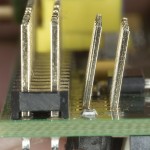
8 holes for P5 header on Raspberry Pi Rev 2. Square = pin 1
Rev 2 Raspberry Pis (including model A) have holes for a P5 header
When I got my first Rev 2 Pi, I was quite keen to try out the P6 reset header since nobody else had blogged about it apart from Eben’s original announcement.
Now I find myself in exactly the same position again regarding the P5 header. I haven’t read a single blog or forum post about anybody using a P5 header. I’ve been thinking about it on and off for weeks. There are some practical issues around it, which is why it’s taken me such a long time to figure out the best way (for me) of overcoming the issues.
So what are the issues?
P5 is right up against the main GPIO header (P1).

P5 conventional options from the top
It was designed to be soldered in from underneath so as not to “foul” the P1 header pins.
OK, but that causes issues, namely…
- makes it hard to use the Pi with a case
- increases the height of the Pi
- is generally awkward
- means you potentially have connections on 4 sides AND two faces of the Pi
- not very aesthetic
…so I’ve been pondering for ages (“for the longest time” as they say in the US) how to overcome this problem. Last night I hit on a possible solution, which is rather “outside the box”. More on that in a minute.
Possible “conventional” solutions are…
- female header on top
- male header on top
- male header underneath
- female header underneath
- right-angled male header underneath
- right-angled female header underneath

Conventional options from below
I even considered soldering wires directly to the through-holes. But that just seemed silly.
None of those ‘did it’ for me
None of the above list quite ‘did it’ for me. The closest would be a right-angled female header underneath. If you snipped off the ends of the 8 protruding pins from P1, you could get this as a ‘flush fit’ and it would be OK – as long as you weren’t using a case. I was going to go with this option until I started fooling around with an angled male header, reversed from underneath. The pins only stuck out the top about 2/3 of normal pin height. And then my hand slipped and the pins angled away from P1. Inspiration struck. :)
“I wonder if I could solder them at a slanted angle pointing away from P1?”

P5 header pins at an angle – get outside that box. :)
OK, it looks a bit “wrong”, I’ll give you that, but consider the upside…
- It doesn’t need wires connecting to underneath
- It doesn’t increase the height of the board
- It should work with any case that works with wires attached to P1 (more or less)
- It doesn’t stop you attaching a Gertboard or ribbon cable
- It should still allow fitting of most “above the Pi” add-on boards (except PiCrust)
You won’t be able to use the pins with most add-on boards attached, but at least it shouldn’t prevent their attachment.
I think we have a winner. ;) Hence the “leaning header of Pi5a” was born. It’s on a Raspberry Pi, header P5 on a model A, hence – Pi5a. Kind of appropriate for a slanted header, don’t you think?
(I think Helen over at the Raspberry Pi Foundation might like that one.)
Tricky soldering the inner pins
It was quite difficult to solder the two inner pins next to P1. In the end there was no choice but to do the six I could reach, then prise the plastic base off the other side and do two from underneath, using a female header (from the top) to get the pin alignment right. Next time I’ll take a female header, push eight bare pins into it, hold from the top and solder from underneath. This will be much easier and should completely avoid getting solder on the pin uppers.
Despite that “learning opportunity”, it worked out really well. All the pins do exactly what they’re supposed to do and all four new ports work fine as outputs. I have yet to test them as inputs, but if they work as outputs, they’ll probably be fine. :)
See for yourself in the video.
___________________________________________
* After I finished this article I found just one reference where someone had documented soldering on a P5 header. And guess what? They chose a very similar approach, but with longer pins
Great video as usual – looks like soldering it was… fun…
It’s easy if you stick all the pins in a female header and hold that from the top. I know that now LOL. ;) It was a little messy doing it “the other” way, but it works, and now we know. Most importantly, though, it works, both physically and electrically. :yes:
Next time (and there will certainly be a next time) I will do it the easy way right from the start. But everyone else can do it that way first time, now it’s obvious. ;)
Hi Alex,
Did you look at option #5 but putting the connector on the other side, i.e. the side that contains the P1 header? Obviously, the straight pins would have to point away from the P1 connector, but there could be room for adding a ribbon cable. It might be tight, or even impossible, because the DSI interface connector (S2) is on the way.
Great video; thanks for putting it together!
Cheers!
Yes there’s not enough space for the pins to be usable in that orientation with the angled male header.
[…] great article by Alex over at RasPi.TV. This time he looking at the best way to solder some header pins to to the P5 header on the […]
[…] from from RasPi.TV spent some time considering how to make use of the unpopulated P5 territory on the RasPi — […]
The route I went was to just remove connector S2 and install a right-angle connector for P5 on the top side of the Pi. Photo here.
Good solution if you are able to remove S2 without problems :) Also shows people nicely how you can’t use that angular header in that spot without removing S2.
Thank you, Alex. And thank you for the article which inspired me to try this hack. I just took a couple more photos, and in them you can see removing S2 didn’t occur without scuffing up the board very slightly. Should anyone want to try it themselves, the trick is to gently pry the plastic of S2 off the pins. It will slide up/off, allowing one to remove the pins individually. Otherwise, you’d need a hot air tool to remove the connector all at once. Anyhow, I should have used a non-metallic tool instead of a screwdriver for prying. Live and learn! :D
Oh, and I should mention one more thing. I didn’t sit P5 flat against the board. This is for two reasons: 1) The key-tab on some cable ends would have made it impossible to slide on otherwise and 2) That pesky C5 is hiding underneath and I didn’t want to inadvertently scrape it off.. :)
C1 and C5 both look pretty exposed now in your macro shots. Teeny little things aren’t they? :) Great stuff.
[…] knew this one was coming last week when I was pondering adding the P5 header. One of the reasons I chose a top-mounted P5 header was so that the Pi could still be […]
so what are p2 and p3 used for?
I think one of them was JTAG header, but I can’t remember which one. I have seen a pinout diagram before. I’ll see if I can find it.
http://elinux.org/RPi_Low-level_peripherals has all the details.
[…] nice and small, so I figured it could go in the case. How to connect it though? Remember the leaning header of Pi5A? I had all sorts of header connectors in stock from that, so I picked out a 2×4 female angled […]
I met AndrewS at the Cambridge Jam today. He showed me another solution for P5 which was really rather good. He used a push-fit type connector. Hopefully he’s going to send over a pic and I’ll show you, then maybe someone can tell us what it’s called :)
Ah! Sorry I kept forgetting – here you go: https://www.dropbox.com/sh/fs8yhavz2u2nxvk/wkk343sjNI
My photography isn’t anywhere as near as good as Alex’s ;-)
DSCF0172.JPG, DSCF0173.JPG and DSCF0174.JPG were just me using other connectors to (try to) keep the two 1×4 connectors aligned during soldering (but they still ended up slightly out of alignment).
If you look closely you can see where I accidentally melted the plastic corner of the DSI connector with my soldering iron – whoops!
The great thing about this approach is that it’s so low-profile, it still fits in a standard case. This looks like what I used: http://www.rapidonline.com/Cables-Connectors/SIL-Single-in-line-Turned-pin-sockets-82700
Excellent – thanks Andrew. I thought they looked similar to the chip sockets on the Tandy Gertboard I bought back in September, but these are single.
Alex,
I am in the process of ordering my first Pi, but have been reading a lot about it thus far. Indeed, your discussion above is quite interesting, though there are other options that I am curious if you considered. One such option would be soldering a small ribbon cable (from under the board) that could be fed through most cases along with a ribbon cable that might otherwise be plugged into the top part of the P1 header.
Even a very small ribbon cable with a header solder or plugged into the other end could be useful.
Have you tried this or considered it? If you are already in the process of doing so, I look forward to seeing your photos, videos, notes, etc…
V/R,
Stuart B. Tener
Computer Scientist
I haven’t tried it, but see no reason why it wouldn’t work, as long as the selected case has enough spare space round the side of the Pi where you want to run the ribbon cable.
Alex,
Well, I am going to have to research what size standard breadboard wire is and see if one end of it can be soldered to the board or not. If so, that would make it quite easy to fish through a case most likely and leave the non-Pi end of it ready to be plugged into a breadboard or other item.
One thing I am going to have to determine as well is if the Pi has holes where standoffs could be put to raise the Pi up in the air, thus making mounting the pins on the P5 connector from down low much easier. That maybe an easy way to do it for me too, since I plan to make a custom box for at least one Pi so it can also house a GPS receiver in the box (I am building a GPS logger and stratum-1 NTP server).
V/R,
Stuart
There are two holes on the Rev 2 board that could be used for standoffs. Pete Lomas doesn’t like them being referred to as mounting holes, but a lot of people use them for this purpose. Just be careful not to tighten the screws/bolts too tightly.
I like soldering pin-header onto ribbon cable to give me a ribbon cable -> breadboard connection :-)
http://www.maplin.co.uk/2.54mm-0.1in.-pin-strip-1500
I’ve also made 4-way and 8-way ribbon cables with pin headers on both ends (when I was playing with Arduino a while ago), since ribbon cables look much neater than many separate wires!
Top-tip: Make sure you cover the solder connections in hot-glue (for strain relief) otherwise they quickly snap with repeated flexing.
[…] made available on a brand new “solder it yourself if you want it” header called P5 (see the leaning header of Pi5a) 8 holes for P5 header on Raspberry Pi Rev 2. Square = pin […]
Very interesting discussion, which I’m clearly coming very late to. It seems to me that you could insert a 4×2 male header pin from the top (and hence easily solder it on the bottom) by leaning it away from P1 before it’s soldered – all it needs is to chamfer with a craft knife the bottom part of the polarising bump on any ribbon cable IDC connector used in P1. I’ve dry fitted it and it seems to work, and looks neater and more consistent with P1 that way. (It’s basically Option 2 but leaning away from P1.). If you get it to lean enough, you may not even need to modify the IDC connector at all (but I’ve already done this – the bump is pointless anyway as this end doesn’t go into a socket, and in fact, it’s a good reminder of which end is which).
Alternatively, if you shave the whole bump off the IDC connector as I’ve done, I believe you can mount the P5 header pins upright on the top (neater still) and still attach a 4×2 header socket on them, with a ribbon cable simultaneously attached to P1.
Before I solder this, have I missed something?
As long as it meets your requirements, go for it.
[…] It’s currently available for £24, which isn’t at all bad for this quality of kit and is only compatible with Revision 2 Pis – the ones with the extra P5 pads. You don’t need to solder a header onto the pads as the card uses an ‘innovative sprung’ mechanism to connect to the pads. (I’m not sure what that looks like in practice, but it sounds like a very cool, and sensible, way of getting around the P5 header dilemma). […]
Another option (a variation on the idea you rejected as silly) would be to solder wires directly to the board and terminate them in a pluggable connector. The cable bundle could be as short as you could manage, but with enough length to make the necessary bends. For cable management, you could use ribbon cable (with the wires held together by their own insulation) or tiny wire ties.
“I think it was a really magnificent oversight that the original Raspberry Pis shipped with the 26 pin GPIO header on.”
I guess that’s an “oversight” that has now been “corrected” with the Pi Zero? ;-)
LOL – yeah