A few days ago, Ben Croston updated the RPi.GPIO Python library so that the ‘board’ pin numbering system would work with all of the pins on the B+. It doesn’t really affect the way I work, as I always use BCM port numbers. They already worked on the B+ and the compute module.
While he was at it, he made a couple of bug-fix tweaks. Looking at what was tweaked, I realised there are a couple of features of RPi.GPIO that I hadn’t yet documented. In this blog post I hope to update my RPi.GPIO documentation. RPi.GPIO 0.5.6 is already in the Raspbian repository, so to update to 0.5.6, just…
sudo apt-get update

sudo apt-get upgrade

y
Edge Detection Addition
In my previous tutorials on threaded callbacks we used edge detection of RISING and FALLING edges. Somewhere along the line, Ben introduced an option to test for BOTH falling and rising edges. I knew about this, but hadn’t tried it before.
So, where previously we had the code…
GPIO.add_event_detect(25, GPIO.RISING, callback=my_callback)
OR
GPIO.add_event_detect(25, GPIO.FALLING, callback=my_callback) for a falling edge
Now we can also detect edges in either changing direction, using BOTH…
GPIO.add_event_detect(25, GPIO.BOTH, callback=my_callback) for either rising or falling edges.
“Hold on”, you say. “That’s all very well, but how do I know whether it’s FALLING or RISING?”
It’s easy, when you think about it. Just read the port using GPIO.input(25) in the callback function. If it’s 0/LOW/False, it was FALLING, and if it’s 1/HIGH/True, it was RISING. As Andrew correctly points out in the comments, it’s a good idea to have as little code as possible in your callback function to avoid missing any transitions while the code is executing.
That’s a bit abstract, so to test it, we’ll need a little circuit and some code.
Let’s Make a Circuit
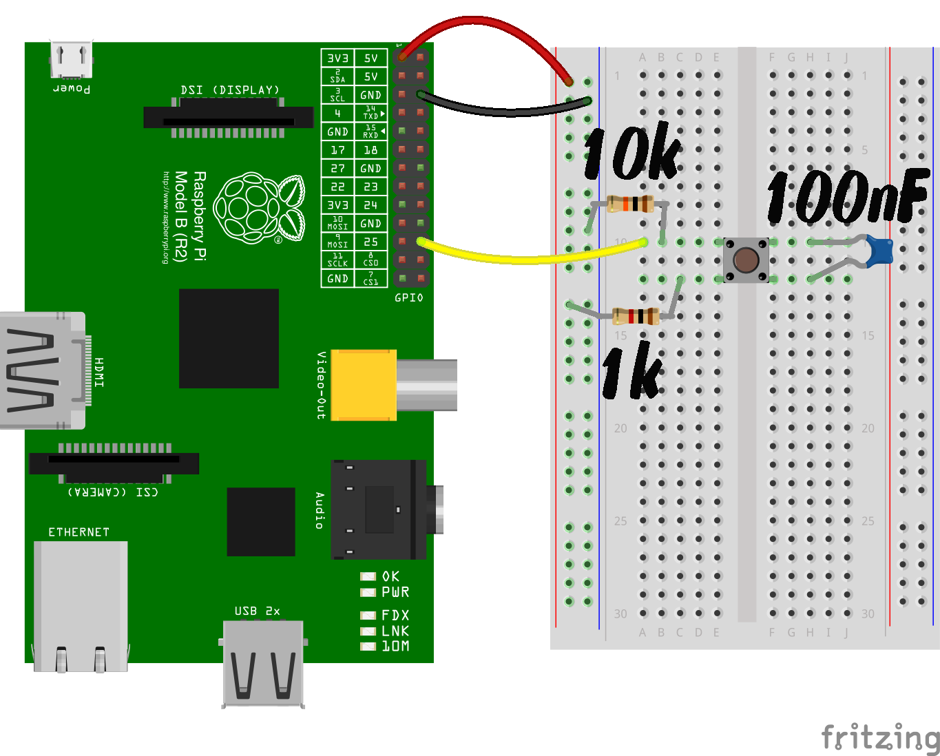
Circuit for testing GPIO.BOTH
The 10k resistor is a pull-down, to give the port a default status of 0/LOW/False.
The 1k resistor is to protect the port.
The 100 nF capacitor is needed in order to see the effect we’re looking for. It debounces the switch in hardware because we’ve removed the ‘bouncetime=300’ from the ‘GPIO.add_event_detect’. We did that so we can see what’s happening in real-time.
When you press the button, 3V3 connects to GPIO 25 (through the 1k resistor) and causes a Rising edge on the port. If you keep the button pressed, nothing should happen. When you release the button, the 10k pull-down resistor will pull GPIO 25 back to GND and a Falling edge will result.
The program ends after 30 seconds.
Here’s what my circuit looked like (I used a 330R instead of a 1k)…
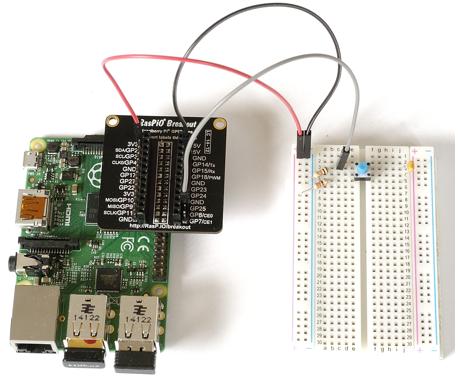
Circuit for testing “BOTH”
Here’s the Full Code
#!/usr/bin/env python2.7
# demo of "BOTH" bi-directional edge detection
# script by Alex Eames https://raspi.tv
# https://raspi.tv/?p=6791

import RPi.GPIO as GPIO
from time import sleep     # this lets us have a time delay (see line 12)

GPIO.setmode(GPIO.BCM)     # set up BCM GPIO numbering
GPIO.setup(25, GPIO.IN)    # set GPIO25 as input (button)

# Define a threaded callback function to run in another thread when events are detected
def my_callback(channel):
    if GPIO.input(25):     # if port 25 == 1
        print "Rising edge detected on 25"
    else:                  # if port 25 != 1
        print "Falling edge detected on 25"

# when a changing edge is detected on port 25, regardless of whatever
# else is happening in the program, the function my_callback will be run
GPIO.add_event_detect(25, GPIO.BOTH, callback=my_callback)

print "Program will finish after 30 seconds or if you press CTRL+C\n"
print "Make sure you have a button connected, pulled down through 10k resistor"
print "to GND and wired so that when pressed it connects"
print "GPIO port 25 (pin 22) to GND (pin 6) through a ~1k resistor\n"

print "Also put a 100 nF capacitor across your switch for hardware debouncing"
print "This is necessary to see the effect we're looking for"
raw_input("Press Enter when ready\n>")

try:
    print "When pressed, you'll see: Rising Edge detected on 25"
    print "When released, you'll see: Falling Edge detected on 25"
    sleep(30)         # wait 30 seconds
    print "Time's up. Finished!"

finally:                   # this block will run no matter how the try block exits
    GPIO.cleanup()         # clean up after yourself
So when you run the program, you should see the wiring instructions, then you press <ENTER> to start.
After that, when you press the button, you get a single “Rising Edge” message and when you release it, you get a single “Falling Edge” message.
Here’s a little video clip to show what should happen…
Hope you enjoyed that little experiment. If you want to learn more about RPi.GPIO and GPIO hacking on the Raspberry Pi, there’s a whole series of tutorials here…
https://raspi.tv/rpi-gpio
RasPiO® GPIO Reference Aids
Our sister site RasPiO has three really useful reference products for Raspberry Pi GPIO work...
Short & sweet :-)
Perhaps it’s worth mentioning that you want to have as little code as possible in your callback functions otherwise you risk missing the ‘opposite’ edge transition while your callback is still executing?
P.S. “affec” is a typo ;)
Good. Updated. Thanks :)
Without thinking to hard, I can’t think of an application where you need to detect both edges of a single pulse.
Measuring the speed of an object (of known size) passing through a light-gate? ;-)
I’ve never needed it either, but some people have. For example Rachel Rayns, the artist in residence at the Raspberry Pi Foundation was asking me about exactly this feature at the recent Cambridge Jam. Although I knew about it, I’d never used it. She wanted to use it in a control system for an exhibit. I suggested this method, and from what I gather it fits the bill perfectly.
I think it was a bit more complex than a push-button though. I think it was to read the state of arduino pins for changes in either direction. The above circuit was just the simplest I could come up with to illustrate the point.
Establishing two call backs for the same GPI pin does not seem to be supported by the library which is a pity.
I considered the above approach to detecting both edges and then discriminating between them but whilst that seems to work the solution suffers from race condition in that the level can change between the time of the callback and discrimination. I would rather be certain which condition the code is acting on.
My solution was to sense my PIR using 2 GPIO lines and establish 2 callbacks – one for the rising edge and the other for the falling edge.
hi can I have this program in C language..plz
I don’t think Alex is a C programmer, but the C source-code for the RPi.GPIO library can be found at http://sourceforge.net/projects/raspberry-gpio-python/ and there are other code-examples on http://elinux.org/RPi_Low-level_peripherals
Or you could ask for help on http://www.raspberrypi.org/forums/viewforum.php?f=33 if you have something specific in mind.
hi alex, need your advice about coin acceptor. i just bought this http://www.aliexpress.com/item/CH-Zinc-alloy-KAI-638-Advanced-CPU-Coin-Selector-Acceptor/496009261.html
i already put a voltage divider so that it will give me a 3.3v. i was thinking to use rising edge when the coin is inserted, does it work or do i need interrupt instead? i don’t know how to detect a fast voltage output so this might work.
If the signal goes to 3v3 when a coin is inserted, a simple rising edge interrupt will work well.
the problem i encounter is that when i insert the coin, because its so fast it only reflects around 0.5 ~ 0.8 volts using an analog voltmeter. i haven’t tested it yet with an oscilloscope. how will i tackle this problem?
Analogue voltmeters are only designed for slow-moving signals, and so display more of an ‘average’ voltage. Systems designed for digital I/O, such as the Raspberry Pi, should have no problem detecting fast-moving signals.
How to run your script demarage?
when I run the script in rc.local, the interrupt does not function
I do my edge detection like this:
addCallback(1, GPIO.RISING, callback1) addCallback(1, GPIO.FALLING, callback2) def addCallback(pin, edge, callback): def callbackWrapper(pin): if edge == GPIO.RISING and GPIO.input(pin): callback() elif edge == GPIO.FALLING and not GPIO.input(pin): callback() GPIO.add_event_detect(pin, GPIO.BOTH, callback=callbackWrapper)This doesn’t really work in newer python version. It gives error as you can’t do “add_event_detect” in newer python versions twice
Hi,
I build myself an Internet Radio, like anyone else.
Using some python radio scripts from “bobrathbone” plus a few changes to the scripts to match my LCD and the board I made for the rotary encoders I got a working system. Anything works great and sounds OK.
The issue I am having, and I have no idea how to debug this, is that after a while there is no reaction to the rotary encoders or buttons. The music plays and the LCD is updated accordingly, so in theory the “radiod” daemon works.
I also made a test by stopping the daemon and after the re-start it worked again all as expected for a while.
What can possibly be the issue here?
Thank you.
why i can’t use GPIO.add_event_detect….. in a while loop ? plz explain for me , thanks
can U explain what you mean… with an example plz?
What isn’t working the way you expect it to?
this is my raw program, image 1,
http://postimg.org/image/b0n9ot3x9/
and it did not work…
result
http://postimg.org/image/fiy48iicj/
The error message is exactly correct – adding a callback is a “one time” thing, you should only do it once (i.e. before your while loop). Once you’ve already added a callback to a GPIO pin, it’ll fire *every* time the event triggers.
I’m sure there’s lots of examples of using a HCSR04 with a Raspberry Pi – I just did a quick search and found http://www.raspberrypi-spy.co.uk/2012/12/ultrasonic-distance-measurement-using-python-part-1/
thank you . Sir Andrews :)
i wrote this for distance sensor HC SR04
Hello!
I’m trying to control two motors and I need to know the time when the 2 pins connected to the encoder change their states in order to calculate the angular velocity. Any suggestions?
https://www.google.co.uk/search?q=raspberry+pi+python+gpio+rotary+encoder might provide a few useful links? Not something I’ve ever played with myself.
That guide was very useful, thank you. I wonder if I can use 475nF capacitor? If capacitor is because of bounce time, can I avoid using capacitor and add bouncetime for event detection?
What would happen if we don’t use that capacitor? Is it compulsory?
You’re likely to get some switch bounce.
If you want to get rid of the capacitor, you can use software debouncing to prevent each switch press or release generating multiple events.
Hi,
I’m currently creating a datalogger on a Raspberry Pi which will record the real time and date of every rising and falling edge of the signal continuously. Therefore I believe my code is practically the same up until line 21. Instead of “from time import sleep” I have “from datetime import datetime”. I also have “import csv” and “from csv import writer”. I was wondering if you could help me with the rest of my code as I am new to python and am stuck on the next steps.
For my next steps I need to continuously detect and record the real time and date of every falling and rising edge of a signal and save this data to a CSV file. The CSV file will have two columns. The first column will be called “Edge type” and will then either say “Falling edge” or “Rising edge” for every detection, obviously depending on whether it is a rising or falling edge. The 2nd column will be called “Date and Time” and will record the real time and date of each detection to a resolution of a millisecond.
Any help would be appreciated.
Thanks
Hi,
I’m currently turning a Raspberry Pi into a datalogger which will record every rising and falling edge of a square wave input signal. Therefore I believe my code is practically the same up until line 21. Instead of line 7 I have “from datetime import datetime” and I also have “import csv” and “from csv import writer”.
My datalogger needs to record the real time (resolution of 1ms) and date of every rising and falling edge and save this to a csv file on a USB attached to the Pi. It needs to record this continuously in an infinite loop. Has anyone got any idea how I would go about coding this? Any help would be appreciated.
Thanks.
is this site still active??
how can I code the following:
if rising edge or falling edge of GPIO 24 (pin18) :
subprocess.call(“/home/pi/on_off”) # on_off is a bash script
Thanks for any help.
regards
thomas