
The HDMIPi driver board is a fairly complex design. I didn’t design it, although I did have some input into the feature list. I don’t fully understand how it works (something to do with the magic white smoke in the chips, I think), but I have messed around with it probably as much as anyone.
Recently, several people have been asking if we can switch HDMIPi on and off programmatically from the Pi. Göran Roseen wants to be able to do it with this HDMIPi based clock…
@Raspberry_Pi wall clock with go-to-school indicator that goes from green to red as time runs shorter. @HDMIPi pic.twitter.com/tbzJjgiXRS
— Göran Roseen (@roseeng) January 12, 2015
…and others want to be be able to do it with time or PIR-sensor control.
Can We Use tvservice? No :(
Some monitors allow you to do this using the “tvservice” command. Whilst this will switch off HDMI output from the Pi, it doesn’t turn off the backlight on HDMIPi, which is the greatest power consumer. (It may be that we can get this into a future version. We’ll see.)
So I got to thinking…
Hold on. We have a power button which can toggle the screen on and off without killing power to the Pi. I know this because it was a feature I wanted in the list. Maybe we could hack that switch and use a GPIO port on the Pi to toggle the screen on and off?
So I decided it would be fun to hack my own product and share the process with you. It took a couple of hours getting this to work. It didn’t work the first time, but I did get it working second time and have now figured out how to make it work well.
Measure Twice, Cut Once
It’s an old carpentry saying, but it applies to a lot of other fields too. Taking good measurements and diagnosing the issue is usually the best first step you can take. I needed to understand what “pressing the power button” actually does, so I could see if I could replicate that with a GPIO port on the Pi.
So I took out my trusty multimeter and made some measurements. I quickly established that pressing the power button shorts one side of the circuit to GND. I also probed the button circuit to see what its voltage was. Higher than 3V3 we’d need a transistor to do the switching for us.
Happily the circuit was 3V3, the same as the Pi’s GPIO ports. Even more happily, the current draw on pressing the button switch was ~0.7 mA. This is small enough that we can just hook a wire straight from the positive side of the button to a GPIO port*. Then if we drive that port LOW it shorts that side of the circuit to GND just like if we pressed the power button. That’s the theory anyway.
I Did Get A Couple Of Things Wrong First Time Though
Initially I completely forgot that the button on the HDMIPi driver board had its own pull-up resistor (explanation here) so I tried to use one of the i2c ports on the Pi. These have their own hardware pullups, so I figured they’d be the best ports to use. The trouble is, when the button +ve side was connected to an i2c port, none of the HDMIPi buttons worked. (I’m not quite sure, but I think the Pi’s pullup may have overwhelmed the 3V3 pullup’s source on the HDMIPi board? WJDK.)
But the buttons worked fine again when the wire was disconnected. So I had a little think and decided to try a different GPIO port. I picked GPIO 25 as it’s the same on all models of Pi and I could route the wire underneath the driver board and Pi and connect from the other side, making the wire almost invisible from outside the case.
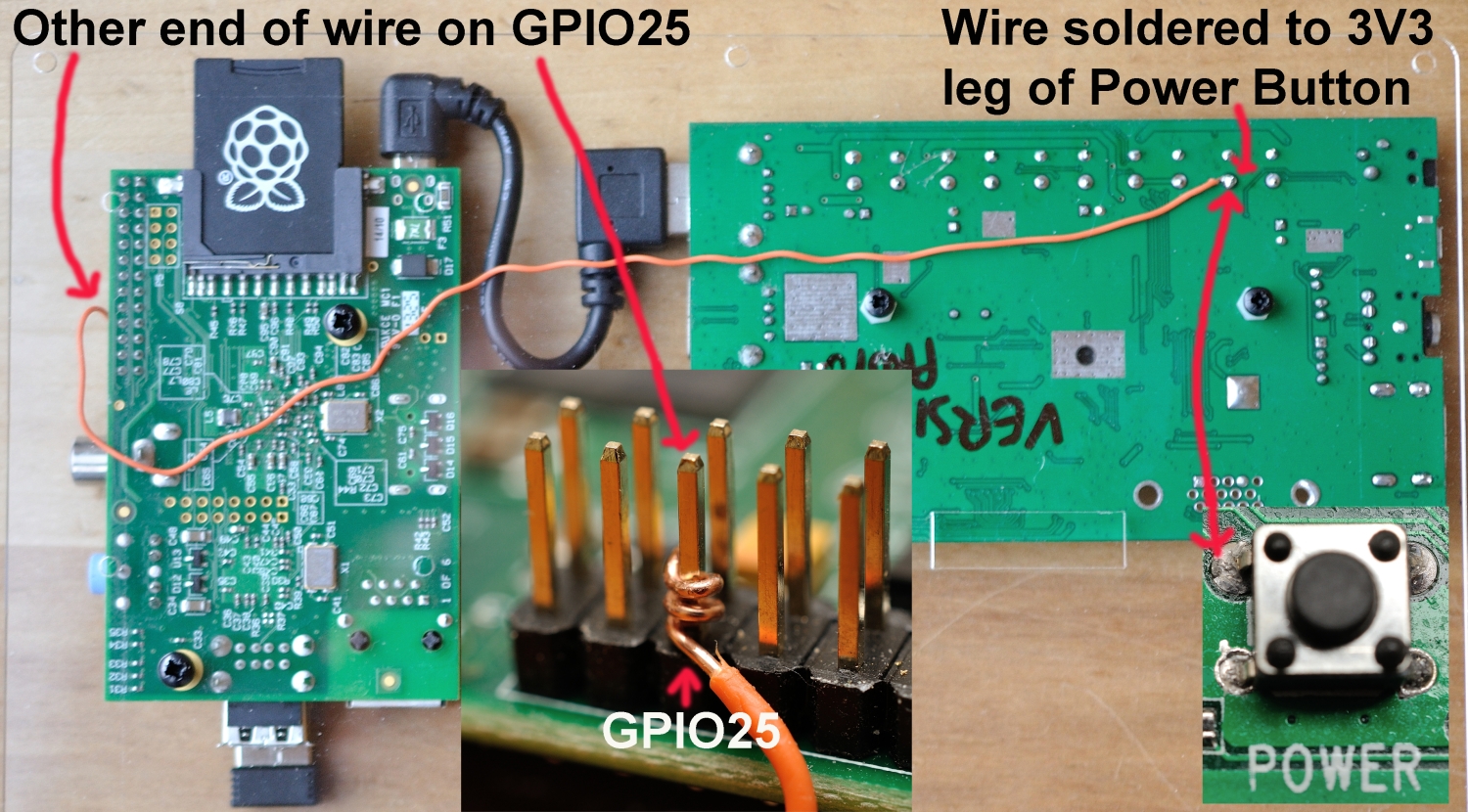
Wire connecting HDMIPi power button to GPIO25
I soldered the wire on the underside of board as I could wrap it round the button leg before soldering. This ensured a good connection and easier working. It also helped me keep the hot iron away from the board, reducing the chance of damage or shorting. The GPIO25 end was wrapped firmly round the GPIO25 pin. I used solid-core copper wire (from a reel of Cat 5e ethernet cable). It was removed and squeezed slightly to make it a firm ‘push-on’ connection.
It Worked, But Still No Buttons!
Having switched ports and removed the 1.2k resistor*, my little program started working, switching the HDMIPi on and off. YAY! But I soon realised that, while the program was running, all the HDMIPi buttons (apart from the power button) were disabled. When the program finished, they worked again.
OK. So something is happening here because the port is being used as an output. As soon as it’s reset to an input the buttons all work again.
So that was the solution. I tweaked the software so that GPIO 25 is only set up as an output while it’s being used to toggle HDMIPi on or off. The rest of the time it’s set up as an input. This means that the HDMIPi pullup resistor and 3V3 source are not overwhelmed (if that’s what’s happening) and are able to perform correctly.
And now BINGO – it all works just as it should :)
Here’s A Video Showing It In Action
Here’s The Python Code
#!/usr/bin/env python2.7
# HDMIPi_toggle.py by Alex Eames https://raspi.tv/?p=7540
import RPi.GPIO as GPIO
from time import sleep
GPIO.setmode(GPIO.BCM)
GPIO.setup(25, GPIO.IN)

# If 25 is set as an input, the hardware pullup on the HDMIPi board
# keeps value at HIGH. We only change the port to an output when we
# want to toggle the button.
# This is because, when set as an output, the HDMIPi buttons are disabled.
# So each time we toggle the HDMIPi on or off, we set port back to input

def toggle():
    GPIO.setup(25, GPIO.OUT, initial=1)
    GPIO.output(25, 0)         # this is our simulated button press
    sleep(0.2)                 # hold button for 0.2 seconds
    GPIO.output(25, 1)         # release button
    GPIO.setup(25, GPIO.IN)    # set port back to input (re-enables buttons)

for x in range(3):             # on for 10s, off for 5s iterate 3 times
    print "HDMIPi will stay on for 10 seconds"
    sleep(9)
    print "HDMIPi is switching off for 5 seconds"
    sleep(1)
    toggle() #off
    sleep(5)
    toggle() #on

print "finished, cleaning up"
GPIO.cleanup()
You could condense the code a bit, but I’ve left it like it is so it’s clear to see how it works. For example, this version of the toggle() function works equally well…
def toggle():
    GPIO.setup(25, GPIO.OUT, initial=0) # simulate button press
    sleep(0.2)                 # hold button for 0.2 seconds
    GPIO.setup(25, GPIO.IN)    # set port back to input (re-enables buttons)
That’s The Basics, Now Make It Your Own!
Obviously this shows just the basic “ON/OFF” functionality. You should probably make it more robust with some exception handling (try: except: finally:) to trap unexpected errors and problems that may arise.
Apart from that, its applications are virtually unlimited. You could use this technique with…
- a cron job for timed switching
- a doorbell and camera
- a twitter app
- a kickstarter tracker
- PIR sensor to detect people
- Light sensor or any other sensor
- An ADC circuit to measure battery voltage and kill power to the screen when battery is low
You Could Even Hack The Other Buttons
While I was writing this article I had a “wow” moment. I realised that if we hacked all the control buttons we could have a programmatically driven OSD menu system. I don’t know if that will ever happen, but it’s nice to think that it could be done. I doubt if I will do it, but anyone who needs or wants it could, if they wanted to. Hackable products for the win!
Will It Affect My Warranty?
I just know that someone will ask that, so I’m pre-empting the question. If your HDMIPi driver board breaks because you have interfered with it, it would be unreasonable to expect a free replacement. But if you know what you’re doing and solder carefully, using the button leg, as I did, there shouldn’t be a problem. (And if there is, we can sell you another one for something in the region of £20.)
————–Notes————–
* Initially I added a 1.2k resistor in series to protect the GPIO port. I later removed it after I’d measured the current.
Nice hack! But wouldn’t it be easier to use a optocoupler (or transistor) in in parallel with the button instead?
Do you really think that’s easier than soldering a wire to the leg of a button and connecting the other end to GPIO25? Personally, I think that would be much more difficult to do. But I’d love to be proved wrong if you have a go at it yourself :)
Your end result is of course much cleaner and easier than adding a optocoupler, but I was thinking about the process of overcoming the obstacle of the non functional buttons. If I would face such a problem, as a beginner in electronics, I would have added a optocoupler as I wouldn’t know effect of ‘overriding’ the pull-up resistor on the HDMIPi board. But I think you’r right: your solution is electronically less complicated, the only advantage of my solution would be a little bit less Python code in your program.
I believe Martien’s solution of an optocoupler would also be the one to use if the HDMIPi and the RPi didn’t share a common GND signal. But of course being connected by both the power lead and the HDMI connection, they share a very good ground :)
Great hack Alex :-D
I think they may well also be ‘grounded’ together through the HDMI as well.
I’ve actually no doubt that Martien’s method is better, but this here is an ‘unashamed raw hack’. Obviously the best way to accomplish this goal would have been to get it incorporated into the product in the first place. It’s possible that it could be a firmware tweak if no input signals are detected (for example). Or maybe there’s a way of doing it with HDMI (that’s beyond my knowledge).
By the way, prompted by a tweet from PeterO, I’ve taken it a stage further. There will be a part 2 to this post :)
“this here is an ‘unashamed raw hack’.”
Oh yeah – quick, cheap and dirty hacks are often the best ;-)
If I wasn’t so busy right now, I’d be very tempted to code up the software-controlled OSD you talked about. Maybe next month…
“Or maybe there’s a way of doing it with HDMI (that’s beyond my knowledge).”
I’ve never used it myself (my TV is too old to support it), but I believe that’s what CEC is all about? Chances are the HDMIPi board doesn’t support it either?
“it could be a firmware tweak…”
If the firmware *is* tweakable (via the unsoldered USB connector perhaps?) I’d love to have an option to have the HDMIPi report it’s native res of 1280×800 over EDID rather than advertising 1080p and then scaling it in hardware. (I frequently test many different OSes, and having to edit config.txt every time becomes a bit of a pain)
Yes. I completely agree. We had problems over the whole EDID thing. Round and round in circles. I believe the firmware is flashable via those pins, but we don’t have the hardware, software files, or know-how to do it. We’d love to though and it would be nice to push the supplier for that capability. It’s been a bit of a learning curve for them and us, but we hope everything will improve as we build on past efforts :)
The chip does support HDMI 1.4 so it may well have CEC capability, but whether or not that’s brought out to the driver board WJDK. ;) We didn’t ask for it, so quite likely we haven’t got it.
Oh. And if you do want to have a go at the OSD thing, drop me an email and I’ll get Dave to send you an extra driver board you can solder things to without any worry about breaking yours. :)
Alex,
there is one other advantage of wiring this direct and that is that you could also detect HDMIPI’s buttons being pressed whenever the GPIO is not configured as an Output. So for example, with one press of a button you could switch on HDMIPI and start up a program on the Pi. The only issue with this is whether it is possible for the Pi to detect whether the HDMIPI is one or Off. Would tvservice help with that?
I’ve found another hardware hack for that detection (just this morning) and will be blogging that as part 2 in a couple of days :)
[…] From RasPi.TV: […]
Hi,
Maybe the wrong topic, but I wonder where I can by a HDMIPI.
If I click the links, I can only find pre-order, but then the links are dead.
Thx,
Chris
This link still works for me http://shop.cyntech.co.uk/products/75-reward-hdmipi-standard
But they are still on pre-order. Hope to clear that within the next few weeks.
Hi, sorry, you are right, links are working (had some local proxy issue).
Hope they will soon be available. I have hughe “hunger” for one :-)
Thx,
Chris
[…] days later this post appeared on […]
I don’t think I’ve done anything wrong, but…
Chuffed to bits to finally get my HDMIPi and love the quality of the screen. I decided that I’d give this hack a go and was pleased that when connected up, the script to turn the screen on and off worked perfectly.
It was only later that I realised that none of the other buttons on the HDMIPi (apart from the power button) work when the wire is connected to the Pi, whether the script is running or not :-/ I’m using a B+ but I don’t see that should make a difference, should it?
Disconnect the wire and everything is back to normal.
Thanks
Simon
Which GPIO port are you using?
GPIO 25, same as here.
Just a thought, but should the type of wire make a difference? I’m just using a breakout wire that I had lying around. I assumed that would be enough and it’s proven working as the toggle script worked fine.
Pretty much any wire should work as long as it doesn’t have too high a resistance I would have thought. I had issues first time around when I had an inline resistor in the circuit.
Good call Alex. It looks like resistance was indeed futile. I’d tried to be a bit clever and had used the end of the breakout wire which was essentially a pin to bend around the gpio pin. I snipped that off and wrapped the bare wire around it and it seems to be working now :)
Thanks for your advice and great product. So glad that I finally got it. Took it into the office today and it got some rather admiring comments :)
Hi Alex,
Thanks for the blog. I have been looking for a way to do exactly the same with PIR sensor. However, the difference with my project is that I don’t have a HDMIPi screen, instead, I got the LCD display from an old laptop, and bought a LCD controller board from ebay (similar to this one http://www.ebay.com/itm/M-NT68676-2A-HDMI-DVI-VGA-Audio-LCD-LED-Screen-Controller-Board-Diy-Monitor-Kit-/110977522562 ) . Do you think I can use the same approach as yours? The LCD controller board and RasPI are using two seperate power supply, so I guess only need to connect the ground?
Worked like a charm… Now I can setup the media board with auto on/off with the IR sensor like I’ve always wanted… Thanks Alex!
Hi Alex
Many thanks, that helped alot. Now i can turn on/of HDMIPi and show UniFi NVR streams when motion/recording is detected by one of the cams. Great work!