
Last week I bought some 4-digit, 7-segment displays to experiment with. Strangely enough it was something I’d never tried before, so I was interested to see how they work. I googled around looking to see if someone else had done this before. It seems there are several different sorts of 7-segment displays, so you have to find a good match for the one you’ve bought.
You can get them in various guises including: i2c backpack; 12 pins; 16 pins; resistors built-in; common anode; common cathode etc.
The ones I bought are 12 pin, bare, no backpack, no PCB, no resistors, common cathode. Here’s what they look like…
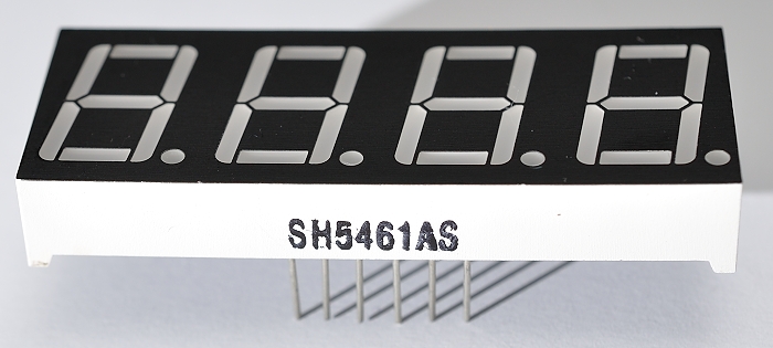
7-segment display
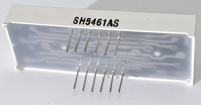
7-segment display – rear
No Datasheet? Google Is Your Friend.
There was no datasheet, so I had to dig around for information. I found two really useful pages which gave me all I needed to know. One was on the Parallax website, which gave me the pinouts, from which I’ve made my own pinout diagram showing the pin numbers and what they do…
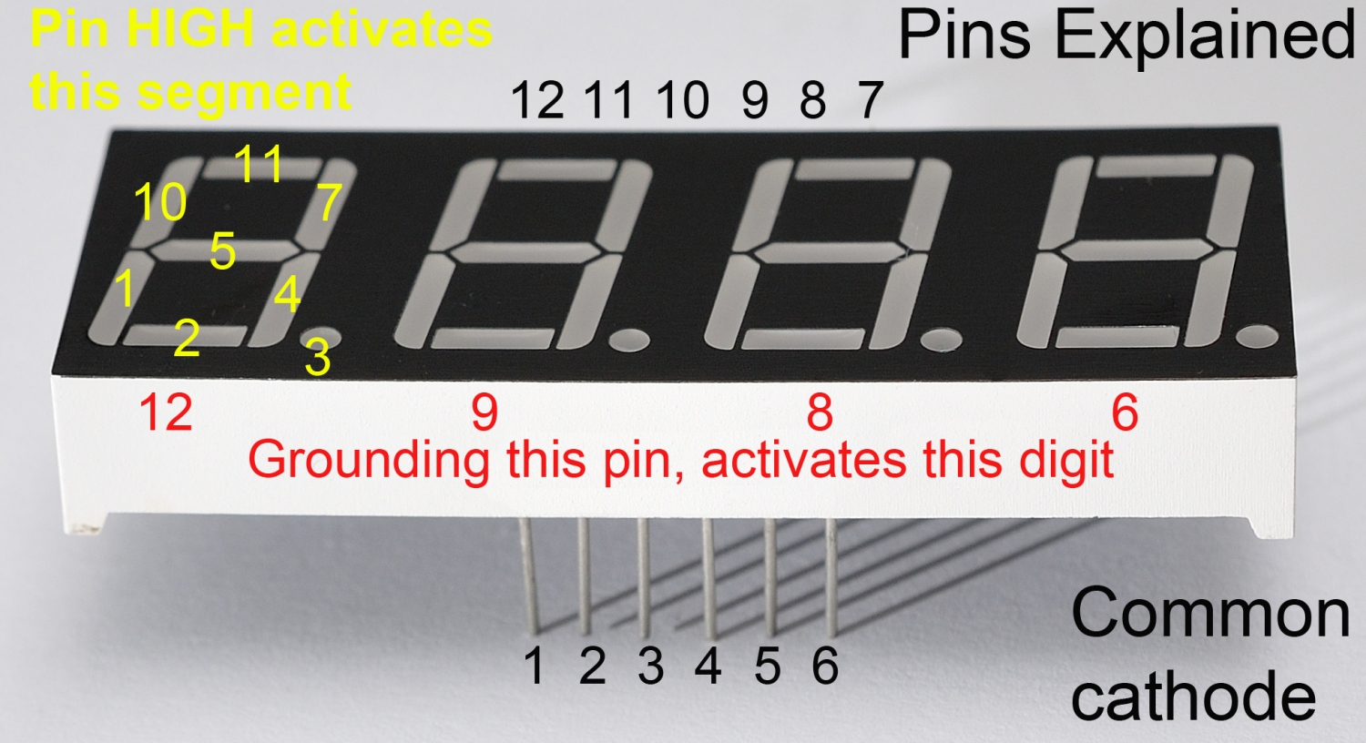
Common cathode 4-digit 7-seg pinouts
How Does It Work?
If you connect pin 12 to GND, the first digit will activate (9 = second, 8 = third, 6 = fourth).
Bringing each of the other 8 pins HIGH activates a specific segment on all currently active digits.
So if we had 12, 9, 8 & 6 all connected to GND, and 7 & 4 HIGH, all four digits would display the number 1.
But How Can We Use That? It’s Impossible?
The way that you get each digit displaying something different is to switch them on and off again, in turn, faster than the eye can observe. Using the same circuitry to control more than one ‘thing’ is called multiplexing. We need some Python code to handle this for us, and we’ll do it using 12 of the Pi’s GPIO pins (4 to switch the digits and 8 to switch the segments).
We also need some current-limiting resistors. 330 Ohm works, but is a bit dim. I’ve opted for 100 Ohm, which gives the LEDs a little protection. In reality, we’re switching fast, so each segment should only be ON for a short time. But if you connect these segments directly to a 3V3 source off-Pi without current-limiting resistors, you will damage or kill the leds in the segments (yes of course I tried it).
OK Let’s Wire It Up!
Here are the connections you need to make…
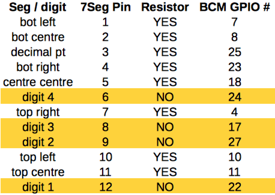
Wiring connections for common cathode 7-segment display
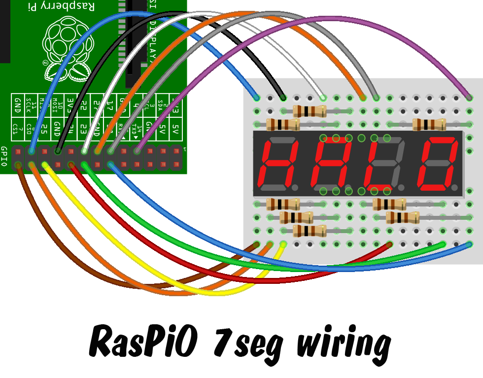
Wiring Diagram for 7-segment display
This is what my finished setup looks like (not quite as pretty as the diagram)…
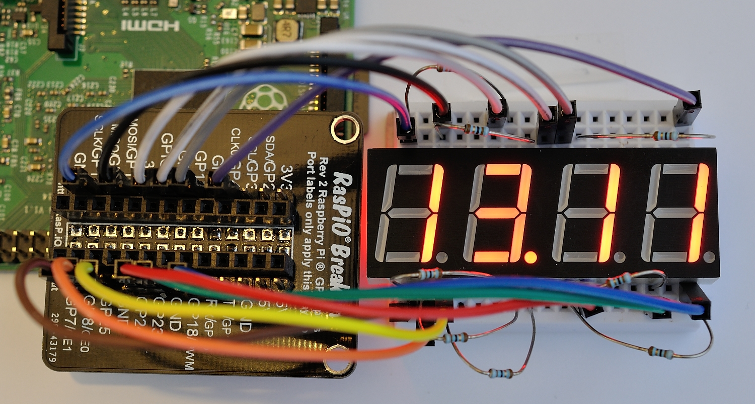
RasPiO 7-segments display clock
I used one of my RasPiO® Breakout boards and a 170 point mini-breadboard to wire up the 7-segment display. This means you can do all the wiring “off-Pi” and then attach the project all at once. For a 12-wire project, this is extremely useful. I wired it directly to the Pi the first time, but when I wanted to re-order the wiring, I found it much easier to use the RasPiO® Breakout. It’s also easy to detach from the Pi without undoing and messing up all the wiring.
What About The Code?
The other useful web page I found was a post in the Raspberry Pi Forums, where Bertwert had published a Python script to turn one of these displays into a clock. That looked like a fun way to test out the new toys, so I gave it a try. I very carefully wired everything up exactly according to the instructions, but only one digit was lit. I checked my wiring. It looked sound. I had another look and eventually realised that the code posted in the forum had messed up indents.
This is one of the hazards of cutting and pasting code, and particularly Python. What it meant was that only one digit was being processed, the others were being passed over. Adding a few well-placed indents helped this to work correctly. There was also a missing colon in the code that caused it to throw an error. As you do, I posted back my amended code for future followers of that thread.
I also tweaked it to eliminate a redundant line, converted it to use BCM GPIO numbers and changed the wiring to make it logical for my chosen layout. The code is posted below…
# code modified, tweaked and tailored from code by bertwert
# on RPi forum thread topic 91796
import RPi.GPIO as GPIO
import time
GPIO.setmode(GPIO.BCM)

# GPIO ports for the 7seg pins
segments =  (11,4,23,8,7,10,18,25)
# 7seg_segment_pins (11,7,4,2,1,10,5,3) +  100R inline

for segment in segments:
    GPIO.setup(segment, GPIO.OUT)
    GPIO.output(segment, 0)

# GPIO ports for the digit 0-3 pins
digits = (22,27,17,24)
# 7seg_digit_pins (12,9,8,6) digits 0-3 respectively

for digit in digits:
    GPIO.setup(digit, GPIO.OUT)
    GPIO.output(digit, 1)

num = {' ':(0,0,0,0,0,0,0),
    '0':(1,1,1,1,1,1,0),
    '1':(0,1,1,0,0,0,0),
    '2':(1,1,0,1,1,0,1),
    '3':(1,1,1,1,0,0,1),
    '4':(0,1,1,0,0,1,1),
    '5':(1,0,1,1,0,1,1),
    '6':(1,0,1,1,1,1,1),
    '7':(1,1,1,0,0,0,0),
    '8':(1,1,1,1,1,1,1),
    '9':(1,1,1,1,0,1,1)}

try:
    while True:
        n = time.ctime()[11:13]+time.ctime()[14:16]
        s = str(n).rjust(4)
        for digit in range(4):
            for loop in range(0,7):
                GPIO.output(segments[loop], num[s[digit]][loop])
                if (int(time.ctime()[18:19])%2 == 0) and (digit == 1):
                    GPIO.output(25, 1)
                else:
                    GPIO.output(25, 0)
            GPIO.output(digits[digit], 0)
            time.sleep(0.001)
            GPIO.output(digits[digit], 1)
finally:
    GPIO.cleanup()
There’s a full code walk-through in the comments below.
Want To Have A Go?
If you’d like to have a go at this project, I have a limited number of kits available for £12 including global shipping. Here’s what’s in the kit. Pick yours up today and start playing with 7-segment displays on your Pi…
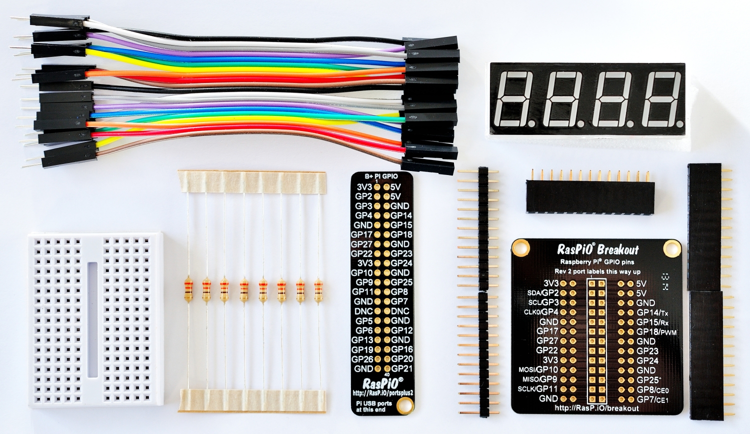
RasPiO 7-segments display tinkering kit
In the next article, we use this 7 segments kit to make a countdown ticker.
Hi Alex – I have ordered the kit and look forward to tinkering with it. In the meanwhile, is it possible to get a detailed explanation of what the code does? In particular, the time.ctime()[11:13] etc parts are beyond me.
Many thanks and keep up the good work. KC
Hi Kieran.
Good point. When I write my own code I usually do a full walk-through don’t I? ctime() is a new one on me also, but I’ll look it up. I didn’t tweak Bertwert’s code much, just mainly switched it from BOARD (which I don’t use) to BCM which I do and changed the wiring.
Your kit is about to go in the post :)
Hi Alex, Thanks for posting and sharing this. I’ve managed to make it work, but cannot figure out how to adjust the time displayed.
Hmm it corrected the time automatically. I still have lots to learn :)
Here’s a code walkthrough…
lines 3-5 import required libraries and set BCM mode
lines 8-13 define and set up the 8 ports for the LED segments
lines 15-21 define and set up the 4 ports for digits
lines 23-33 create a dictionary to hold the values for each segment to display each number 0-9 and null
lines 35-50 are wrapped in a try: finally: block to catch any errors or exceptions and clean up the GPIO ports on exit
lines 36-48 contain the main program loop which carries on until we terminate with CTRL+C or some error/exception occurs
line 37
time.ctime()give us the current time in the form: ‘Mon Nov 16 14:11:05 2015’time.ctime()[11:13]gives us a ‘slice’ of this output starting at the 11th character and stopping at, but not including, the 13th. This gives us the hour.In the same way,
time.ctime()[14:16]gives us the minute. Together, the whole expressionn = time.ctime()[11:13]+time.ctime()[14:16]gives us a string variable, n containing the current hour and minute values.line 38
s = str(n).rjust(4)since the output ofctime()is a string, thestr()is redundant (I didn’t spot that before).nis already a string variable.rjust(4), as you might guess from the name, right justifies our string,nand pads it with space characters as required (not in this case). So now we have a string variable,s, containing our four figure value of current time:1411lines 39-48 iterate through each digit in turn, left to right.
lines 40-45 determine which LED segments should be switched on, then 46-48 cause the current digit’s enable pin to be grounded for a millisecond. So each of the active segments will display on the current digit. Then the loop iterates round the other digits, before going back to the start of the main loop and checking the time again.
lines 40-45 iterate through the segments to set up the ports to display each number.
line 41
GPIO.output(segments[loop]sets the current segment’s port according to the value it finds in the dictionary we created earliernum[s[digit]][loop]looks horribly complex, but let’s break it down. For each port we want a 0 or a 1 to turn it on or off.We have all the correct values stored in our dictionary
num. We have our four digits stored in variablesand our current loop counterdigittells us which of the four digits we want. sonum[s[digit]]looks in our dictionarynumfor the nth figure ins, which will be a string value 0-9. With me so far?A Python dictionary works as a key:value pair. So,
num['9']will output the values corresponding to ‘9’. We don’t want them all though, so we add[loop]to cut it down to just the specific segment we want right now in this loop iteration.So the output from
num[s[digit]][loop]will be a single integer value 0 or 1, which is used to switch the corresponding GPIO port for the current segment Off or On.lines 42-45 control the flashing ‘dot’ which remains on for even seconds and off for odd seconds, giving an indication of the passage of seconds.
lines 46-48, as already mentioned, these cause the correct digit to be enabled for a millisecond so that its value can be displayed, before going onto the next digit.
49-50 ensure a clean exit when the program terminates for any reason (in conjunction with line 35
try:)Hi Alex,
Fantastic tutorial! It took me about 2 hours to wire it all up, the last thing that I was expecting it to do was work first time, BUT IT DID!
Thanks a lot and keep up the good work.
It’s always great when that happens. And you know what? It happens more and more as time goes by, but it never stops feeling great.
The Joy of STEM ;-)
time.ctime() returns a string, like this:
‘Mon Nov 16 22:08:00 2015′
So time.ctime()[11:13] would the hour, i.e. ’22’
and time.ctime()[14:16] would be the minute, i.e. ’08’
All the Best
Julian N.
Nice article Alex. I’m sure I have one of these in my bits box somewhere. I was going to attempt to use it with a MAX7219 following a previous article you wrote, but this looks like a simpler way of doing things.
They’re lots of fun. I’m refactoring the code and am going to do something else with it soon :) I realised after David Meiklejohn tweeted at me this morning, that Bertwert’s code could be somewhat condensed, which also makes it easier to understand.
You know what it’s like with your robot series. Once you get into something fun/interesting, you have to keep tinkering until you can make it dance how you want :)
Got a number of suggestions I could make to the Python code here, but rather than wade in I’m going to wait until my 7-segments kit turns up so that I can check my improvements actually work on real hardware first ;-)
For now, I’ll just suggest that the seconds-indicator-code
if (int(time.ctime()[18:19])%2 == 0) and (digit == 1):
GPIO.output(25, 1)
else:
GPIO.output(25, 0)
could be placed above the
for loop in range(0,7):
line. No need to run the same thing 7 times!
Haha Andrew. I’ll be making some changes myself in tomorrow’s blog. I’ve made several tweaks. (Yours is in the post now so should be with you in a day or two.)
Looks like what I did last year:
http://www.instructables.com/id/Controlling-a-7-segment-4-digit-display-with-a-Ras/
https://www.raspberrypi.org/forums/viewtopic.php?f=37&t=91796
Great minds think alike, we both described the resistors with a chart: “Pin -> Resistor -> Pi”
Great job!
It was largely based on your forum thread bertwert. Thanks for posting it :)
Didn’t notice you mentioned me in this post :D
I got one and it worked first time – it’s painful connecting all the wires though! Great idea.
Is it possible to,get a white display though instead of the red
Glad it worked. :)
It’s possible to get hold of different colours but I don’t have them.
I got some here:
http://www.ebay.co.uk/itm/121031922000?_trksid=p2060353.m2749.l2649&ssPageName=STRK%3AMEBIDX%3AIT
Hi Alex,
Love the kit and I’ve placed an order for it. I’m a horticulture student and looking at raspberrys for temp/humidity/ EC sensors. I’m hoping I can tie in the display with a hygrometer sensor I have on its way to me. My idea is to have the sensor connected to a pi with a display to show current readings, but also have it internet connected so real time readings can be taken, also have alerts sent by email if certain parameters (e.g. soil gets to dry) are breached . My only problem is I have no clue when it comes to coding. Can you help or guide me at all?
Regards,
Rob.
I’ll offer my usual tips: start small, work on one small piece at a time, gradually work your way up; don’t dive in at the deep end and try to tackle everything at once.
The old “learn to walk before you try running” ;-)
IMHO the Raspberry Pi forums http://www.raspberrypi.org/forums/ are a much better place to ask for the kind of help you’re looking for.
Hi,
Would this kit work for the Raspberry pi 2?
Best,
Austin
Yes it works on all models of Pi.
Hey, nice tutorial
One question: What kind of resistors are you using (in terms of ohm)?
Around 100 Ohm. You could get away with lower as long as you didn’t leave the segments illuminated 100% of the time.
No need to use MegaOhm or GigaOhm – Ohm M G ! ;-)
Hello again,
I’ve got some C code which provides me with a variable containing the room temperature (measured by a sensor connected to RPi). Now i want that value to be displayed on the 7 segment 4 digit display. Is there any possibilty to implement Python into C or to compile Python into C?
What sensor are you using? If it’s a common one, there’s a good chance there’s already been a Python module or sample code written to read it.
Alternatively if your sensor-code is *only* available in C, what I’d do in your situation would be to write a small ‘wrapper’ C program (i.e. compile it to a standalone executable) which when called simply prints out the current sensor value. And then from within your python code, call the external executable using https://docs.python.org/2/library/subprocess.html and read its output.
Or you could go the other way round, and use http://wiringpi.com/ to control the GPIOs driving the 7-segment display directly from your C code…
Dear Alex,
I recently bought from you the kit. Do you know if a can show a python string in the segments?, I have now something like this:
myFile = 'youtubesubs.txt' # this calls the text filemyFile = open(myFile, mode= 'r') # opens in readmode
# read all file contents
lastLine = myFile.readlines()[-1] # read the last line
n = 6 # splits the string each 6 characters
splitted = [lastLine[i:i+n] for i in range(0, len(lastLine), n)]
print(splitted[0])
That prints this string on the console:
2.183
Thank you!!
It should be possible if you feed your variable splitted[0] into variable n on line 37 instead of the time. But the decimal point might need some extra code to sort it out.
Hi! do you know if I can add a ‘.’ in the dictionary to by able to show numbers like this?: 2.234. I received the kit today, all working perfectly, thank you :-)
Hi Adrian. The decimal point (dp) is controlled by port 25 in this scheme. It is possible to include it in the dictionary, but the code would need some refactoring. Depending on what you’re doing it might be easier to control it separately.
Thank you! Yes, in this case I’ll do it separately
I’ve written a little program (which you’re free to adapt for your own purposes) which can display any number (integer or decimal) between -999 and 9999
https://gist.github.com/lurch/c6965457172a1b89a8bc
It automatically displays the minus sign and/or decimal point where necessary :-)
Thank you Alex,
Right now is working without the decimal point, but I’m going to check this other code for improve mine.
bye!
Sorry, Andrew, not Alex, everybody here starts with A… :-D
It’s so we can get our alliterations done right.
Another alphabetically astute answer allowing Andrew, Adrian and Alex astonishing amusement :)
Absolutely awesome and amazing ;)
It’s fairly easy to convert this to a common anode display like the one I bought.
Essentially, you put 1’s where all the 0’s are :-)
My swapped version of the software is here: https://github.com/JulianNicholls/Raspberry-Pi-Misc/blob/master/python/gpio/4x7seg-ca.py
If you have any questions or want other help, reply here.
The file has been renamed to clock-ca.py and it’s here:https://github.com/JulianNicholls/Raspberry-Pi-Misc/blob/master/python/gpio/clock-ca.py
Here is mine finished!! Counting youtube subscribers. I’m looking for made another one but with 8 digits, any ideas how to start? I’m not sure if I have enough room in the gpio for another 4 digits :-S
https://www.dropbox.com/s/5jibk65d2w4rosk/File%2002-03-16%2011%2027%2059.jpeg?dl=0
The way that multiplexing works, means that to add another 4 digits (to expand it from 4 digits to 8 digits) only needs another 4 GPIO lines :-)
Using the pin-numbers from Alex’s photo above (and assuming your 4-digit 7-segment displays are identical) you’d simply connect each of the LED-pins 1,2,3,4,5,7,10,11 together in parallel, and then the LED-pins 6,8,9,12 from each display would connect separately to different GPIO pins on the Pi (using 8 + 4 + 4 = 16 GPIOs in total).
And then you’d simply modify Alex’s code above to make the Pi think it’s talking to a single 8-digit 7-segment display.
Thank you Andrew! I’ll give it a try and comment here :-)
Is there a way to output a 12 hour as opposed to a 24 hour clock?
yes – without actually looking at the code (using my phone at the moment), find the bit which deals with hours and then do a simple if statement something like this…
if hours > 12:
    hours = hours - 12
(I’ve given a method here without spoon-feeding the code – having now looked at the code it is a bit more involved.)
Thanks. I’ll try my best to make it work. I’m building a controller for large 12v LED digits. Each one is in its own 18″x24″ frame and I’m using seconds also, for a total of 6 digits. So there will have to be a lot of modifying of this design. But I think it’ll work. My biggest concern is running the 12V LED’s from a second power source and with a common ground. I don’t think the raspberry pi can handle that much current on its own.
Hi guys,
I’m trying to follow your tutorial and i’m stuck at this point. It prints the last number sended on each digit. I can decide to print or not on each digit but i can’t control the displayed number.
For example : string_display = “1234”;
digit to prints = [0,2]
Will display:
| 4 | | 4 | |
Any ideas ?
Without seeing your full code, it’s impossible to know what’s going wrong. But what you _could_ try is:
string_display = '1234'
digits_to_print = [0, 2]
new_chars = [' '] * len(string_display)
for d in digits_to_print:
    new_chars[d] = string_display[d]

new_string = ''.join(new_chars)
which would give you a new_string of ‘1 3 ‘ which you can then display using Alex’s code above.
Hi AndrewS and thank you for your time ! :)
I tried the python clock and the python ticker ( just inverting 0 and 1 in the library )
As is, it will display numbers faster than my eyes can read it.
So, i’ve just added a small sleep between each draw
and in both cases, it displays always the same number on each digit.
my 7segment ref is “3641BS” ( actually not the same as in the tutorial )
Any ideas ?
here’s my code (sorry for this, i didn’t reach the “code” button ) :
# code modified, tweaked and tailored from code by bertwert
# on RPi forum thread topic 91796
import RPi.GPIO as GPIO
import time
GPIO.setmode(GPIO.BCM)
# GPIO ports for the 7seg pins
segments = (11,4,23,8,7,10,18,25)
# 7seg_segment_pins (11,7,4,2,1,10,5,3) + 100R inline
for segment in segments:
GPIO.setup(segment, GPIO.OUT)
GPIO.output(segment, 0)
# GPIO ports for the digit 0-3 pins
digits = (22,27,17,24)
# 7seg_digit_pins (12,9,8,6) digits 0-3 respectively
for digit in digits:
GPIO.setup(digit, GPIO.OUT)
GPIO.output(digit, 1)
num = {‘ ‘:(1,1,1,1,1,1,1,1),
‘0’:(0,0,0,0,0,0,1,1),
‘1’:(1,0,0,1,1,1,1,1),
‘2’:(0,0,1,0,0,1,0,1),
‘3’:(0,0,0,0,1,1,0,1),
‘4’:(1,0,0,1,1,0,0,1),
‘5’:(0,1,0,0,1,0,0,1),
‘6’:(0,1,0,0,0,0,0,1),
‘7’:(0,0,0,1,1,1,1,1),
‘8’:(0,0,0,0,0,0,0,1),
‘9’:(0,0,0,0,1,0,0,1),
‘B’:(1,1,0,0,0,0,0,1),
‘y’:(1,0,0,0,1,0,0,1),
‘E’:(0,1,1,0,0,0,0,1),
‘1’:(0,0,0,1,0,0,0,1),
‘L’:(1,1,1,0,0,0,1,1),
‘X’:(1,0,0,1,0,0,0,1)}
try:
while True:
n = time.ctime()[11:13]+time.ctime()[14:16]
s = str(n).rjust(4)
for digit in range(4):
for loop in range(0,7):
GPIO.output(segments[loop], num[s[digit]][loop])
if (int(time.ctime()[18:19])%2 == 0) and (digit == 1):
GPIO.output(25, 1)
else:
GPIO.output(25, 0)
GPIO.output(digits[digit], 0)
time.sleep(0.001)
GPIO.output(digits[digit], 1)
time.sleep(0.3)
finally:
GPIO.cleanup()
Hi Alex
For my own clock project, which I’ll document when it’s done, I’m using this display which has a colon (to flash the seconds). It has 14 pins – the two extra ones are for the colon and the other twelve match exactly the display you have above, which makes life easy.
http://www.ebay.co.uk/itm/4-digit-7-segment-red-common-cathode-clock-display-0-56-/131308401635?hash=item1e929733e3
Hi Alex, Great Post, thank you success!
Having banged my head against it for a while last night got up this morning to make the link between the BCM number not being the same as the pin numbers on the pi! https://pinout.xyz/pinout/pin5_gpio3 School boy I know but alas success.
https://www.dropbox.com/s/ndk9mpk173t15ny/2016-10-14%2007.55.43.jpg?dl=0
would it be possible to include a if statement to remove the leading zero so for anything less than 10:00 the leading zero was blank?
Thanks for posting this tutorial! If you want a single segment to display your Raspberry IP address, I modified it slightly:
# code modified, tweaked and tailored from code by bertwert
# on RPi forum thread topic 91796
import RPi.GPIO as GPIO
from time import sleep
import socket
import commands
GPIO.setmode(GPIO.BCM)
cmd=”(hostname -I) || true”
output= commands.getstatusoutput(cmd)
MyIp=output[1] #return eth0 IP address
#MyIP=MyIp.split(“.”) #split by subnet
#MyIPstr=MyIP[3].zfill(4) #Get last number with leading zeros
# GPIO ports for the 7seg pins
segments = (11,4,23,8,7,10,18,25) #GPIO numbers of 7 segment display
for segment in segments: #define output and turn off
GPIO.setup(segment, GPIO.OUT)
GPIO.output(segment, 0)
# GPIO ports for the digit 0-3 pins
# digits = (22,27,17,24)
digits = (22) #only 1 digit
# 7seg_digit_pins (12,9,8,6) digits 0-3 respectively
#for digit in digits: #set display base pin to ground (turn digit on)
GPIO.setup(digits, GPIO.OUT)
GPIO.output(digits, 0)
num = {‘ ‘:(0,0,0,0,0,0,0,0),
‘0’:(1,1,1,1,1,1,0,0),
‘1’:(0,1,1,0,0,0,0,0),
‘2’:(1,1,0,1,1,0,1,0),
‘3’:(1,1,1,1,0,0,1,0),
‘4’:(0,1,1,0,0,1,1,0),
‘5’:(1,0,1,1,0,1,1,0),
‘6’:(1,0,1,1,1,1,1,0),
‘7’:(1,1,1,0,0,0,0,0),
‘8’:(1,1,1,1,1,1,1,0),
‘9’:(1,1,1,1,0,1,1,0),
‘.’:(0,0,0,0,0,0,0,1)}
try:
while True:
for digit in range(len(MyIp)):
for loop1 in range(75): #keep looping for about 1 second
for loop2 in range(0,8):
GPIO.output(int(segments[loop2]), num[MyIp[digit]] [loop2])
sleep(0.001)
GPIO.output(22, 1)
#sleep(0.05) #sleep after digit are printed
GPIO.output(22, 0)
sleep(1)
finally:
GPIO.cleanup()
Better to move below section into the while True loop. Then it updates whenever the connection breaks or establishes.
cmd=”(hostname -I) || true”
output= commands.getstatusoutput(cmd)
MyIp=output[1] #return eth0 IP address
Hi!
I have a question about the code.
In the loop “for loop in range(0,7):” you’re stating each GPIO to True for every segment needing light. Okay but you don’t light them now, you light them a bit further with “GPIO.output(digits[digit], 0)” right?
What I don’t understand is this: if I need to display an “8.”, with your code I will power on 8 leds simultaneously for about 0.001s okay? But… every led consume about 13mA and 8*13 = 104. It doesn’t respect the 50mA total rule! Even for a very short perdiod, are you sure it doesn’t damage GPIO controller ?
What about limiting two or tree segments for a very short time and then light another bunch for leds but not all leds if needed simultaneously? Wouldn’t be safer?
Where did you get the 13 mA figure from? I don’t think each segment pulls that much current in this setup. In any case, nobody trying this has reported a failure, so I don’t think it’s an issue. I haven’t specifically measured the current draw of each segment, but also remember that each digit is only lit 1/4 of the time in the above script.
import os
os.environ[‘TZ’] = ‘US/Eastern’
then change that to your time zone. else the clock will display in UTC
If you have the Pi set up for the proper timezone, it will show properly. I set my pi to my local timezone. The code is just pulling the current time from the OS. So whatever it reports is displayed.
I appreciate the blog. I had some 2.25″ 7-segments that I wasn’t using that I multiplexed together and I’m applying your concept to them. My prototype worked great with smaller versions. Working on the big one now.
Hi, Alex.
I am VERY new to using the Raspberry Pi, however I was thinking of building a digital clock. Initially I bought a clock kit using a Raspberry Pi Zero W. I’ve learnt a little of the programming from making that kit. However it isn’t possible to do what I wanted with the kit and it uses a MAX6951 chip to interface to the Pi so is different to program from your clock. I’ve seen your clock and wondered about expanding it. What I want to do is build a clock using larger LED displays (50mm) for the main display i.e. HH:MM:SS and smaller displays (25mm) for DD:MM:YY below. I know I will need to interface these displays with transistors to allow them to be driven with a higher voltage, probably 12VDC. My question revolves around the GPIO ports, by my reckoning to drive all those displays I would need 12 ports for each digit + a further 7 for the segments, total 19 ports. I’m not planning on using the DP, I will create the colons by using fixed LEDs. As a further add-on I was thinking of a DAY display using two alphanumeric 11 segment displays to give MO, TU, WE, TH, FR, SA & SU. so a further 2 ports plus these displays have 11 segments, so a further 4 ports for the additional segments, giving a total of 25 GPIO ports used. I was puzzled in your python code why you did not use the port numbers in order i.e. 2,3,4,5 etc. You used 11,4,23,8,7,10,18,25, why was that? The Raspberry Pi that I am planning on using is a Pi 3 Model B, and has 26 GPIO ports. Are some of some of those reserved i.e. not usable? Sorry this is such a long explanation but I hope it makes clear what I am planning to do. Any advice would be appreciated.
Anthony
Good question. And the answer may not be obvious – until you know!
When I publish documentation I work kind of backwards. If you look at the wiring diagram/photo you will see exactly why I chose the ports the way I did. I avoid the i2c ports (because they have hardware pull-ups) but apart from that the port order was chosen exclusively so that the diagram and photo would be clear to the users.
So essentially it’s determined by the hardware layout. Not many people work this way though.
That’s great to know, and I’ve also learnt a little bit more about the Raspberry Pi, if I avoid the i2c ports I will be 1 port short, maybe I’ll do without the day indicator. Anyway small steps, I plan to start with the 4 digit clock and work up. It’s great to start learning about a new product, it’s really taken me back to the days of self assembly computers I.e. The Sinclair ZX80 and learning Z80 machine code to make the most use of that 1k of memory. Thank you for your explanation, and yes it does make sense now you’ve explained it.
AIUI the hardware pull-ups on the i2c ports just means that if you configure them as ‘inputs’, then anything externally reading those pins would read a ‘high’ value instead of a floating value. But as you’re going to be using them as ‘outputs’, then it’s fine to drive them high or low, without any problems. When in output mode, the Pi’s GPIO pins are “strong enough” to override any external pull-up resistors.
Thanks for that info, very useful. However I have decided to take a different path now. After reading a lot and building a kit using Pi Zero W, I have decided to use a MAX7221 to drive the displays. Thanks to a lot of quick learning to program in C by reading someone elses work, I think I can acheive what I want. I do know about the different voltage levels. Although it seems that in some cases the Pi will drive the MAX7221 directly, there are a few examples on this very site. If its a problem I think a MAX3379 voltage translator should work, lets just hope my soldering skills are up to that, as it only comes in a 14-TSSOP surface mount package.
im a child and i got it working perfectly with no supervision or help thanks for the post
Well done :)
Hi Alex
I have just bought your kit which I hope to use with an RPi I set up several years ago to monitor and log temperatures in a room (link below). That has been running successfully for several years now.
I intend to use the display to show the current temp instead of having to run the web server my setup offers.
Despite having set that temp Logger up, I am quite a noob when it comes to this so forgive me if I ask a stupid question:
Where would I put your .py file and how do I get it to automatically run when the RPi boots?
The temp Logger software currently running uses a cron command to get the data and write to an SQL database so I have no idea how to do that.
http://raspberrywebserver.com/cgiscripting/rpi-temperature-logger/building-an-sqlite-temperature-logger.html
The answer depends on what version of Raspbian you’re using.
In the old days before Raspbian Jessie, all you had to do was add a line with
“python path/to/file/name.py” in rc.local and it would start on boot.
These days it’s a bit more involved since the switch to systemd
Matt Hawkins wrote a great post about it which I refer to each time I do this…
https://www.raspberrypi-spy.co.uk/2015/10/how-to-autorun-a-python-script-on-boot-using-systemd/
Thanks for your reply.
The setup is running Wheezy and I intend to clone it and start adding the display from there.
I have been reading up a little and realise it is more complex. I would not only need to run your .py file to drive the display, but also to query the temp perature prob say every minute, all without locking the Apache web server and other cron jobs that are running.
I currently don’t know if the display loop in your .py file would lock me out of everything else.
I guess a crude solution would be to modify the temperature-logger to also periodically write out the current temperature to a file e.g. /tmp/temperature, and then you could have a separate script (the Pi is quite capable of running multiple separate scripts at once) reading the value from the /tmp/temperature file, and displaying the number on the display.
Ah ha!
I was wondering how to have a global value for the temp, writing it to a file that can be accessed is a great idea!
Crude? Hey, if it works it works.
Also, rather than get the Temp Logger part to do that, since its primary role is to add to a data base every 15 mins, a separate logger fired with a cron job every minute could provide the required temp value.
I have some experience with Visual Basic for Windows but pretty much new to both Linux and Python.
Thanks a bunch Alex, looking forward to getting your kit and making a start on this.
TypeError: tuple indices must be integerss, not tuple
Perhaps you’ve made a typo in your code?
Cruel ;p
Sorry, didn’t mean to sound cruel, the more polite version of my answer would be:
I’m sure Alex would have tested his code before posting it online, and nobody else has complained about a TypeError, so perhaps you accidentally made a mistake when typing it in. Could you double-check that what you’ve typed in matches the code Alex has in the article?
Alternatively, maybe you could copy’n’paste your code to somewhere like pastebin.com to see if somebody can spot your mistake?
I thought it was a “witty cruel pun” as in TypeError ~ Typo
Hi – I just purchased your kit and am looking forward to using your code to display a strava API (via this project idea: https://www.instructables.com/id/Raspberry-Pi-Strava-Monitor/) Do you have any tips on directing the 7 segment LED code for this use? Thanks!
Ok let me get this straight. You’re going to use the strava scroller python program as an example showing you how to use the Strava api, but instead of using it with a scroll phat, you’re using one of these 7-segs?
It should be doable, but you’re going to have to rip out all the scroll phat code and plumb in the 7seg code instead. Try to take it in smallish bites. Personally I’d figure out the API first and see if you can get the information you want to out of your account and print it on the Pi’s screen.
As a separate thing, wire up the 7-seg kit and run the demo program to make sure it’s working.
Once you’ve got your head around both sides, start to bring them together. That’s how I’d tackle it, anyway. Good luck and have fun. :)
Thanks Alex – I’ll give it a go and will let you know how it comes out :)
Hi – I bought a couple of your excellent kits, but have a minor problem. How do I get the brightness of the segments the same (they differ depending on how many segments are lit – ie a ‘1’ (with two segments lit) is much brighter than ‘8’ (with seven segments lit) etc.).
(I’ve used the parts of the two kits to extend the display to show HH:MM:SS:FF where FF are frames (25 per second). That all works and was fun learning Python from my 14 year old kid – brought back memories of coding 35 years ago!)
Cheers
I’m really not sure how you could do this using direct GPIO drive of the segments.
Sounds like you might be hitting the limits of the 3V3 bus on the Pi?
If you’ve mis-wired the display to have a single (shared) resistor on the ‘common’ pin, instead of having separate resistors for each of the segments, then that would explain the behaviour you’re seeing (I made the same mistake many years ago when I used a 7-segment display for the first time).
But if the display is wired correctly (i.e. you’ve followed Alex’s instructions above) and you are indeed hitting the current-limits of the Pi’s 3V3 bus, then perhaps a workaround might be to use (the same) higher-value per-segment resistors, which would reduce the per-segment current enough that they’d be the same brightness regardless of whether one segment is lit or all segments are lit?
Thanks Alex & Andrew. I’m fairly sure I haven’t miss-soldered but will check again, then try the resistors. It’s also a very old Pi so could well be low current from the board. Will check and let you know! Cheers, Steven
Alex! I have one question. I am new to this raspberry pi thing and when i entered your code, after i type finally: it shows me i have a syntax error. Can you help me?
The full sentence it says is:
SyntaxError : unindent does not match any outer indentation level
It’s hard, for me, to understand this sentence, because English is my second language. Look forward to hearing from you.
Python is whitespace-sensitive, which means you need to have the correct number of spaces at the start of each line, or Python won’t be able to understand your code. Double-check how many space characters you have at the start of each line, and make sure you’re not mixing space and tab characters.
I tried every possible space and tab solution.
I have solved the whitespace problem. Now i have another one. Display is displaying 6.6.6.6 and after a minute it goes to 7.7.7.7
“I tried every possible space and tab solution. … I have solved the whitespace problem.”
LOL. Perseverance gets there in the end :)
If all the digits are displaying the same number, that sounds like a wiring problem. Perhaps two connections are touching when they shouldn’t be?
No, there are no connections touching. I checked multiple times. I also tried to reenter the code multiple times and it’s still showing the same number
There’s definitely a problem somewhere… could it be a faulty breadboard? *shrug*
I have just changed the breadboard. Still doesn’t work. You are supposed to work in a Python shell right? And are you supposed to enter your local time on line 37?
No, you’re supposed to type (or copy) the code into a separate file (e.g. myfile.py), and run it from the command line with e.g. ‘python myfile.py’
I struggled over the same problem. But finally i found the solution. The problem is simple: Our displays work reverse! This mean that high and low have to be switched. Change line 13+21, 0 to 1 and 0 to 1. Lines 23-33, swap all 0 and 1. And finally line 46+48, 0 to 1 and 1 to 0.
Hope it helps some one.
Greets
Hi Alex, thanks for sharing this. I’m super new to electronics, and I built my first 7-segment display by following your article. I updated your code to display a string of any length in marquee fashion https://www.youtube.com/watch?v=QD8sGbLVgig
Here’s the updated code. You may run it like `python marquee.py “hello there”`
“`
# Modified https://raspi.tv/2015/how-to-drive-a-7-segment-display-directly-on-raspberry-pi-in-python
# by oebilgen@gmail.com
import RPi.GPIO as GPIO
import time
import sys
GPIO.setwarnings(False)
GPIO.setmode(GPIO.BCM)
# GPIO ports for the 7seg pins
segments = (11, 4, 23, 8, 7, 10, 18, 25)
# 7seg_segment_pins (11,7,4,2,1,10,5,3) + 100R inline
for segment in segments:
GPIO.setup(segment, GPIO.OUT)
GPIO.output(segment, 0)
# GPIO ports for the digit 0-3 pins
digits = (22, 27, 17, 24)
# 7seg_digit_pins (12,9,8,6) digits 0-3 respectively
for digit in digits:
GPIO.setup(digit, GPIO.OUT)
GPIO.output(digit, 1)
# 0: top
# 1: top right
# 2: bottom right
# 3: bottom
# 4: bottom left
# 5: bottom top
# 6: middle
num = {
‘ ‘: (0, 0, 0, 0, 0, 0, 0),
‘0’: (1, 1, 1, 1, 1, 1, 0),
‘1’: (0, 1, 1, 0, 0, 0, 0),
‘2’: (1, 1, 0, 1, 1, 0, 1),
‘3’: (1, 1, 1, 1, 0, 0, 1),
‘4’: (0, 1, 1, 0, 0, 1, 1),
‘5’: (1, 0, 1, 1, 0, 1, 1),
‘6’: (1, 0, 1, 1, 1, 1, 1),
‘7’: (1, 1, 1, 0, 0, 0, 0),
‘8’: (1, 1, 1, 1, 1, 1, 1),
‘9’: (1, 1, 1, 0, 0, 1, 1),
‘A’: (1, 1, 1, 0, 1, 1, 1),
‘B’: (0, 0, 1, 1, 1, 1, 1),
‘C’: (1, 0, 0, 1, 1, 1, 0),
‘D’: (0, 1, 1, 1, 1, 0, 1),
‘E’: (1, 0, 0, 1, 1, 1, 1),
‘F’: (1, 0, 0, 0, 1, 1, 1),
‘G’: (1, 0, 1, 1, 1, 1, 1),
‘H’: (0, 1, 1, 0, 1, 1, 1),
‘I’: (0, 1, 1, 0, 0, 0, 0),
‘J’: (0, 1, 1, 1, 0, 0, 0),
‘K’: (1, 0, 1, 0, 1, 1, 1),
‘L’: (0, 0, 0, 1, 1, 1, 0),
‘M’: (1, 1, 1, 1, 0, 0, 1),
‘N’: (1, 1, 1, 0, 1, 1, 0),
‘O’: (1, 1, 1, 1, 1, 1, 0),
‘P’: (1, 1, 0, 0, 1, 1, 1),
‘Q’: (1, 1, 1, 0, 0, 1, 1),
‘R’: (0, 0, 0, 0, 1, 0, 1),
‘S’: (1, 0, 1, 1, 0, 1, 1),
‘T’: (0, 0, 0, 1, 1, 1, 1),
‘U’: (0, 1, 1, 1, 1, 1, 0),
‘V’: (0, 1, 0, 0, 1, 1, 1),
‘W’: (1, 0, 1, 1, 1, 0, 0),
‘X’: (0, 0, 1, 0, 0, 1, 1),
‘Y’: (0, 1, 1, 1, 0, 1, 1),
‘Z’: (1, 1, 0, 1, 1, 0, 1),
‘!’: (0, 1, 1, 0, 0, 0, 0),
‘?’: (1, 1, 0, 0, 1, 0, 1),
‘@’: (1, 1, 1, 1, 0, 1, 1),
‘-‘: (0, 0, 0, 0, 0, 0, 1),
‘_’: (0, 0, 0, 1, 0, 0, 0),
}
if len(sys.argv) != 2:
print “Please type the text as parameter (e.g. python type.py \”hello there\”)”
sys.exit(1)
PADDING = ” ” * 4
text = PADDING + sys.argv[1].upper() + PADDING
i = -1
old_binary = None
try:
while i < len(text) – 4:
new_binary = (int(time.ctime()[18:19]) % 2 == 0)
if old_binary != new_binary:
i = i + 1
old_binary = new_binary
s = text[i:i + 4]
for digit in range(4):
for loop in range(0, 7):
d = num[s[digit]][loop]
GPIO.output(segments[loop], d)
GPIO.output(25, 0)
GPIO.output(digits[digit], 0)
time.sleep(0.001)
GPIO.output(digits[digit], 1)
finally:
GPIO.cleanup()
“`
Love your clock tutorial. I am looking for a driver for bigger displays type Kingbright SC40-19EWA.
I am running this program still on a Raspberry Pi 2
Alex,
Have you ever tried to display 6 digits? I want to include seconds also.
This article has been in use for quite some time. I was surprised to see that there wasn’t a function / module to drive this cheap unit I got as part of kit that I bought. Using this article as a starting point, I was able to create a function and a class that took any number, perform some error checking, and then output the code to the LED’s. I also added the decimal point when necessary. I used it for making a temp display for an LM35 that flashes between Celsius and Fahrenheit with just LED.display(Fahrenheit,2). The 2nd variable is for how long to leave the number displayed. I am adding this page as a credit for when I post my code at GitHub.
I found this really useful when figuring out how to add the same kind of display to a BBC micro:bit. I’ve now tried this with a Raspberry Pi, using slightly different arrangement of GPIO pins, on an original model B Raspberry Pi and it works, but the display flickers every second or so in a very predictable way. The flicker seems to be in the same pattern each time of segments getting brighter and dimmer very rapidly in a burst and it’s steady the rest of the time. It does this regardless of what’s on the display (e.g. disabling the second blinking decimal point has no effect). Is that something I can expect to see because of the way Python runs or do I have a problem somewhere? cheers