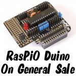
Having completed the KickStarter fulfilment a long way ahead of schedule, we’re now ready to launch RasPiO® Duino on general sale. We thought it would be nice to launch it officially today at the Cambridge Jam.
What Is A RasPiO® Duino?
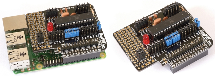
RasPiO® Duino is a small plug-on board for Raspberry Pi. It has similar functionality to an Arduino Uno, but is fully programmable from the Raspberry Pi. Once programmed, it can be removed from the Pi and used on its own.
If you’re interested in the full product description you can find that here.
Free Arduino Programming eBook
RasPiO® Duino has been specifically designed to help people get into Arduino programming on the Raspberry Pi.
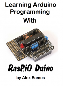
The RasPiO® Duino user guide is called Learn Arduino Programming with RasPiO® Duino. It contains all the information you need to get into Arduino programming on the Pi…
- brief technical information
- a brief build guide (with links to in-depth assembly instructions)
- comprehensive software installation instructions
- lots of example sketches and walk-throughs showing how to use the capabilities of the board
- links to the RasPiO Duino github repository
- an easy-install script for the sketches
- high-quality diagrams and photographs
- 47 pages of educational inspiration, discovery and fun
You can download it here, or by clicking the cover image.
Now Available
You can now purchase a RasPiO® Duino from The Pi Hut, Pimoroni, Ryanteck and Pi-Supply.


Alex, I had mine via the kick starter and it works fine. Is there any chance of seeing the schematic wiring diagram of the RasPIO Duino.
regards
derek
Hi Derek
Actually there isn’t a schematic. I did the design straight onto the PCB.
Thats is good news for both the RPI and Arduino lovers! High quality hardware and documentation!
Did you get my order for a twin pack delivered to the netherlands? It’s just that I’ve not had a confirmation email or anything yet.
Hi Andy. Posted yesterday. There should have been an order confirmation from PayPal. I might need to tweak some settings somewhere if there wasn’t one.
Very Impressed, ordered 10pm Sunday, received 2pm Tuesday, up and running 5pm Tuesday. Many Thanks
Alex – I got the kit put together (well done – it’s a nice piece of kit) without burning my fingers, and it works well, but I am having a problem with the Arduino software. On trying to upload a sketch, I get a
avrdude: verification error; content mismatch
which is fatal. If I then go to Tools->Burn Bootloader this fails, but it seems to clear the memory, so that a re-attempt to upload a sketch then works.
Have you come across this?
Glad it went together well :)
No I haven’t come across that issue. Are you uploading your sketches using “Upload with programmer” like it says in the manual? If you do it with just “Upload” it tries to use a non-existent serial port (I think) and fails.
Yes – of course – I had fallen in to the lazy habit of just using the Upload arrow, which of course is not the same as upload using programmer.
Thanks – looking forward to more exciting projects
Help – I have now assembled the second kit I purchased and it is working after a fashion, but it appears to be running much slower than the first one. On the ‘Blink’ program I have to change the time delay from 1000 ms to something like 84 or 85 ms to get the same rate of flash that I had with the first kit. What have I done wrong? I have double and triple checked my soldering especially around the crystal and capacitors but it still runs slower than the other kit. Any ideas?
Hi Peter.
You have probably omitted to run ./avrsetup on the second board, which sets up the microcontroller :)
That was exactly what I had done. I was obviously too eager to test the second board and missed out that step. Thanks very much for putting me right so promptly, I’m very grateful.
Alex, my ‘Duino Kit arrived and writing modules to the ATMEGA worked perfectly first time. However I find the Arduino IDE too limiting – as I want to use the many modules out there written in C for I²C modules, I would like to ask what the AVRDUDE command line looks like to use it together with other Linux IDE’s like Geany or Eclipse + avr-gcc compiler.
Maybe worth an appendix to the otherwise super pdf.
David, I’m hoping someone else will be able to chip in with the answer to that one because I simply don’t know.
Slowly getting there – at least I can now read the target’s signature the Raspberry, will try to integrate into Geany / Eclipse in the course of the day.
~/avrdude -c gpio -p atmega328p
avrdude: AVR device initialized and ready to accept instructions
Reading | ################################################## | 100% 0.00s
avrdude: Device signature = 0x1e950f
avrdude: safemode: Fuses OK
avrdude done. Thank you.
First attempt (in 65 years) at soldering!. Spent Sunday afternoon working through the video.Success. Works fine blinking and flip flopping.
Great product, documentation and video tutorials, all at an unbelievable low price.
Thanks Alex – brilliant.
Thanks Allan. Always lovely to hear that :)
Saw the tweet also – nice way to start the week.
For me many things came over like ” I have an all singing dancing soldering iron but I am not using it because the chances are YOU wont have one” ( or similar words). That, is what makes this a great supported product.
Oh heck can’t keeping playing…….must go and cut the grass!
Regards
Allan
Hi Alex.
Got my self one of these nice boards, and got it working nicely.
Is it ok for question here?
I seem to hit a wall when it comes to something that should be real simple.
After programming a modified version of the button sketch in AVRDUDE and testing it with LED’s on your board, I take of the atmega chip and put it on the breadboard.
I cannot seem to get the right pins connected at this point.
Doing a search on google atmega328p pins give me a lot of options and the ones i tried did not help.
Do you have a pin reference after the chips is removed?
Here is the code if your interested :)
This example code is in the public domain.
http://www.arduino.cc/en/Tutorial/Button
Hi Ken
Always best to go straight to the official data sheet…
http://www.atmel.com/images/Atmel-8271-8-bit-AVR-Microcontroller-ATmega48A-48PA-88A-88PA-168A-168PA-328-328P_datasheet_Complete.pdf#page=3
It’s the one labelled 28 PDIP
Good, thank you.
I feel this is something I should know but just to clear it up.
When the code in avrdude is saying ledPin = 6; does it refer to the pin as counted from top ending up on GND, or does it refer to PD6, ending on pin 12?
PD6 – it’s all in the comprehensive manual (I’m pretty sure)
Alright. Thank you for answering my low level questions.
Have a great weekend :)