Sep 212012
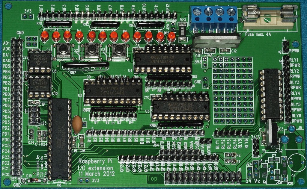
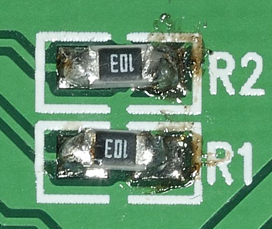
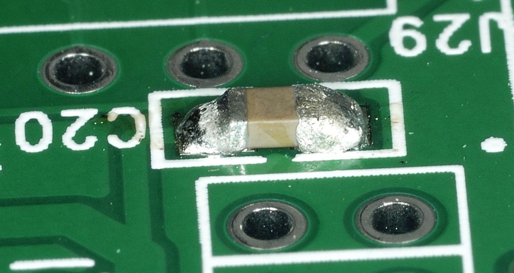
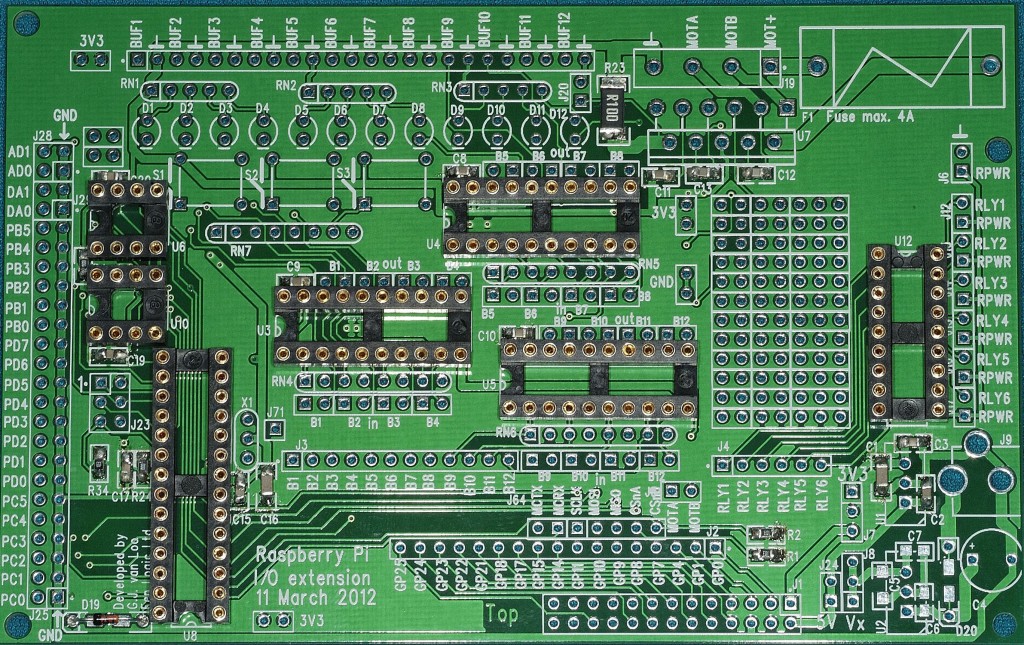
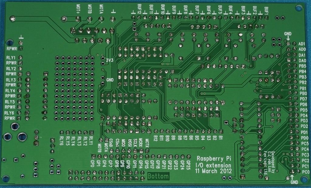
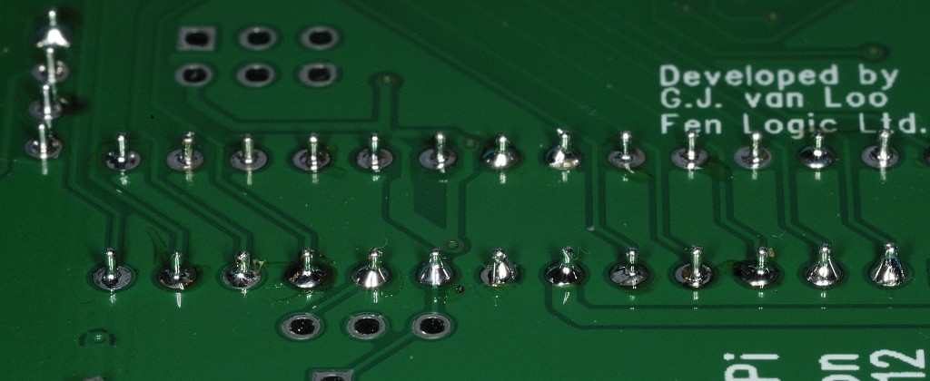
Just finished soldering the Gertboard together. Tested the voltage and it came in at 3.34V, which is within tolerance of the target 3.3V. So, next up will be to make it do something, but I thought you should all see it now it’s done. ;) You can click any of these shots to get the full sized version. No comments about RN7 ;)
I’ll stick up some assembly shots in a little bit.
In the meantime, here’s the thread where people are talking about their Gertboard Assemblies.
http://www.raspberrypi.org/phpBB3/viewtopic.php?f=42&t=17987
Just ordered mine today!
Can I ask though, how do you power the board itself?
Keep up the good work, great web site :)
It’s powered through the ribbon cable which attaches it to the raspberry pi itself. In other words it’s powered from the Pi. It doesn’t draw much though, but obviously that depends on what you attach to it. There is a space for an external supply, but the parts aren’t included in the kit. There was a comment about it earlier in the week by Gert in the Gertboard section of the Pi forums about different ways to power the board. here’s a link