Ever since getting the LCD working and temperature and light level logging using COSM and the Pi Cobbler, I’ve wanted to compact all of this onto a single add-on board.
I’ve mentioned this in forum posts and other blog articles, but a part of me thought it wouldn’t happen. It took me a few weeks to bring it all together, but it’s finally done and it works :)
The circuit
I don’t have a full circuit diagram. I may try to put one together later. :) It’s a bit messy

The back of the board. Here be dragons.
but I’ll try to describe the important bits.

RasPi.TV Weather Station
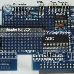
Two analog temperature sensors (TMP-36) are connected to 3V3 and GND and the middle pins connected to channels 1 & 2 of the analog to digital converter. (Connected to the two 3 pin headers at the top of the photo.)
A voltage divider (right centre near the chips) made up of two resistors (20k and 10k) splits 3V3 voltage into 1.1V and 2.2V. The 1.1V feeds into a dual op-amp (small chip), set up as a voltage follower. One op-amp gives a steady 1.1V to the reference voltage pin (Vref) of the Analog to digital converter (large chip). The other op-amp feeds 1.1V to two light sensors (LDRs), which in turn are grounded with 20k pull-down resistors (top centre). The non-grounded ends of these resistors are connected to channels 3 & 4 of the ADC.
A 16 pin header socket supports and connects the LCD.
The rest of it is just wiring up the various necessary connections to the Pi, which I’ll outline in the next section.
The connections to RasPi
Four GPIO ports handle the Analog to Digital Converter, which can connect up to 8 channels. I’m only using 4 at the moment, but even with 8 channels connected, it would still only use 4 GPIO ports.
Six GPIO ports control the LCD (used in 4 bit mode – to use in 8 bit mode would need 10 ports)
Two ports; SDA and SCL handle the i2c barometric pressure sensor
Breadboard and PCB calibration differences
Once it was all up and running, it was time to calibrate the temperature sensors. When I did the breadboard circuit, I had to add about 2 degrees to each sensor to get accurate readings. The first thing I noticed with the PCB version was that the readings were both about 2 degrees too high. So that correction factor was removed. Other than that, I had to add 0.1 to one of them so that they would both read the same side by side with my reference thermometer. The only thing I can think that would make a 2 degree correction factor necessary on the breadboard would be poor quality connections, or maybe the ribbon cable caused a small (~20 mV) voltage drop?
Having to calibrate it for each Pi
I set this up on one Raspberry Pi, but am intending to run it on another one. One thing I noticed straight away when moving it to the second Pi was that the temperature readings were different. A quick measure of the input voltage to Vref showed that this Pi was giving a slightly higher voltage (1124 mV compared with 1115 mV for the other Pi). When 1 mV is approximately 0.1 degrees, a difference of 9 mV is nearly a degree. This is noticeable. So it was necessary to tweak the program to use the exact Vref voltage for each Pi separately. It must be due to small differences in the 3V3 voltage regulator.
This shows that you can’t just switch from one Pi to another and assume everything will be exactly the same. Test and measure. :)
Hi Alex.
Great job. Wouldn’t worry too much about the wiring ‘mess’ – the only reason PCBs look so ‘neat’ is because you can’t really see where the connections zigzag all over the place! Glad I saw this before I did something similar – I was going to solder the LCD directly onto the breakout board. Eeek!
Time to show my ignorance… Be gentle.
What does the A2D converter actually _do_?
I’ve got my Pi using a TMP102 to read temperature, and it does it okay, I just read the value and convert it, and there’s no A2D chip helping it. Is the A2D necessary because you’re using TMP36s or does it make the reading more accurate, or something?
Not sure ‘blissfully’ ignorant is the right phrase – been trying to get my head around it for ages!
Hi Mike.
Yours seems to be a digital thermometer, so you won’t need an ADC as there is one already onboard. What my ADC does it convert the analog voltage output from the sensor into a number between 0 and 1023 so that the computer can process it.
If you have a larger number of sensors (up to 8) it handles them all for you with only four GPIO ports.
Nothing intrinsically wrong with soldering the LCD to the board, it’s just rather permanent. :)
I’d suggest using a stable reference voltage, something like an ICL8069 for example: http://pdfserv.maxim-ic.com/en/ds/ICL8069.pdf
Thanks. Looks like they’ve stopped making that one, but yes that would eliminate the need to calibrate to the individual Pi. Good idea. :)
Hi,
Any chance on making your Python scripts available ?
I’m a total n00b but until now I succeeded every Adafruit tutorial, now I need help to put it all together. How do I connect a photocell AND a thermometer to the ADC an log those values to Cosm (for example) ?
In the end, my personal goal is to have a DIY home automation that triggers a certain relay when it gets dark, another when it gets too hot etc …
I have limited Python knowledge but I can copy/paste and tweak them a little bit for my usage, unfortunately I have no electronic knowledge AT ALL.
Hmmm. The main problem with that – and indeed a major reason why I haven’t done so is that the script is highly customised to my own situation, almost completely undocumented and, although it works, still rather experimental.
With published stuff you have to be rather more careful/responsible. For example, the Gertboard scripts I released are tested, documented and peer reviewed (as well as discussed in forums).
The other thing is that I’m still considering whether to commercialise this with a custom PCB (to get rid of all those ugly wires and make it easier for people to make). If I do that, I will probably release the software to go with the PCB.
Don’t hear me wrong. I’m not saying “no, never”, I might be saying “not yet”. I still haven’t decided yet. :-)
p.s. I think you’ll like my upcoming blog post, which will be about using relays. ;)
Awesome project! Do you have any interest in turning this into a printed circuit board? We’d like to team with you to make this a reality. Please contact if interested.
Justin
[…] me backtrack and explain why I wanted to do this in the first place. I have a weather station running on a Raspberry Pi. It logs the following data to […]