Lithium polymer batteries are light and powerful, but they can’t be run completely flat or they are ruined. I’ve been using them for several years to fly model planes, so I have plenty of them around. I’ve also been using them at Raspberry Jam meetings to power some of my Pi demos.
I thought it would be fun to make a circuit so the Pi could monitor its own battery voltage. I used an analog to digital converter (mcp3002) and had the Pi check the battery voltage every minute and shut down when the battery was too low.

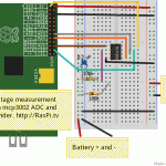
Pi battery measurement setup
You need a way to reduce the Voltage
The main “issue” with this measurement is that the ADC can only handle up to 3.3 Volts (when connected to Pi). A 2 cell lithium polymer (lipo) battery is 8.4V when fully charged and 7.4V when empty (resting Voltage). So we need a way of dropping the voltage from 8.4V to something at or below 3.3V. The cheapest and easiest way to do this is with a voltage divider – essentially two resistors connected across the supply you want to measure. The resistor values are chosen so that the meaured voltage can be divided down to the required level.

Voltage divider explanation
I chose fairly high value resistors to ensure a very small amount of wasted current (it’s a duration test after all). I used 100 kOhm (R1) on the GND side and 180 kOhm (R2) on the +ve side. This meant that the input voltage (8.4 max) would be split as follows…
8.4V * 100,000 Ohm / (100,000 + 180,000) Ohm = 3.0V (close enough to 3.3V (3V3) plus a safety margin)
So how did it work?
I tested each element before the ‘final run’ and, although it shut down a few hours earlier than my optimistically projected 15-16 hrs, the system worked perfectly. It shut down after 9.5 hours, when the battery voltage reached the cutoff level of 3.7 V/cell (2 cells, = 7.4V overall).

Small 2000 mAh 2s2p lipo
Considering the size of the battery pack, 9.5 hours is pretty reasonable.
Projections
Here’s how I calculated how long the battery should last.
The, rather old, 2 cell lipo has a nominal value of 2000 mAh or 2 Amp.hours
2 Ah * 7.9 V = 15.8 Watt.hours
* 0.85 efficiency = 13.4 Wh (regulator is ~ 85% efficient on 3 cells, so this is a guess for 2 cells)
Model A with Edimax dongle uses 0.81 Watts
13.41 / 0.81 = 16.5 hours
But this was wrong – it conked out after 9.5 hours and the battery only took 1550 mAh on recharging.
Bearing in mind that recharging is not 100% efficient, we can see why it lasted a bit more than half the predicted duration.
Still, 9.5 hours is pretty good for a nice portable application.
So, if you’re still awake after all that electronics and maths, here’s what you need to repeat the experiment for yourself…
Requirements
Gmail account (to have the script send you an email when it shuts down)
Python 2.7
RPi.GPIO (it’s already included in Raspbian since August 2012)
Shopping list of parts
ADC (I used mcp3002)
Resistors for voltage divider
A small capacitor (I used 0.1 uF – this may not be strictly necessary)
Some jumper wires
A breadboard or prototyping board (you could use a Gertboard too)
Download this script
batt_test_raspi.tv.py.gz
or, straight from Pi command line…
wget https://raspi.tv/download/batt_test_raspi.tv.py.gz
gunzip batt_test_raspi.tv.py.gz
Then you’ll need to open the script and set some variables.
nano batt_test_raspi.tv.py
Which lines to tweak?
You MUST set the email variables.
# email variables

fromaddr = 'your_gmail_account@gmail.com'

toaddr  = 'destination email address'

# Googlemail login details

username = 'your googlemail/gmail username'

password = 'your googlemail/gmail password'
Optionally, you can tailor other variables to your needs…
# voltage divider connected to channel 0 of mcp3002

adcs = [0] # 0 battery voltage divider

reps = 10 # how many times to take each measurement for averaging

cutoff = 7.5 # cutoff voltage for the battery

previous_voltage = cutoff + 1 # initial value

time_between_readings = 60 # seconds between clusters of readings
# Define Pins/Ports
SPICLK = 8 # FOUR SPI ports on the ADC
SPIMISO = 23
SPIMOSI = 24
SPICS = 25
Then save and exit
CTRL+o

ENTER

CTRL+X
Hooking it all up
You’ll need to wire up your circuit next. In case it’s not clear, the battery is connected to a 5V regulator, which powers the Pi. We also have direct connections from the battery to the voltage divider.

Circuit for Raspberry Pi battery monitoring
Running the script
Once your circuit is wired up, power up the Pi with your battery/regulator and run the script. I ran it using screen so I could detach from it and log off (in order not to waste battery power).
Run the script with
sudo python batt_test_raspi.tv.py

This is what happens on the screen
If you have SPI enabled, you’ll get a warning, which you can ignore.
You’ll then see it takes a reading every minute and displays the ADC reading, the Voltage measured, and what it’s writing to the log file battery_log.txt (which you can look at afterwards nano battery_log.txt)
It looks like this…
Battery log data

2013-03-03 13:29:55, 8.266

2013-03-03 13:30:56, 8.275

2013-03-03 13:31:56, 8.266

...............BIG SNIP.............

2013-03-03 22:57:00, 7.399

2013-03-03 22:58:07, 7.399

Shutting down due to low V at 2013-03-03 22:58:10
No geeky science experiment would be complete without a graph, so here’s a graph of the complete voltage log.

2s2p lipo voltage with time, until auto cutoff
If you happen to be watching in the last two minutes before it switches off, you’ll see it telling you it’s sent an email and giving a shutdown warning. I had the script email my phone so I knew when it had shut down.
I hope this has been fun and educational. :)
_____________________________
If you are going to use this with a higher voltage battery you will need to change the values of the resistors to step the ADC input voltage down to a maximum of 3V3.
Interesting and timely. I’m playing with something similar for a small mobile robot, using one Li-Po and a tiny step-up regulator. Current plan (no pun intended) is to use an AVR for the stuff Pi isn’t good at, including monitoring the battery voltage. I’m planning to shutdown at about 3.1 or 3.2 volts (on load) – do you think that is too low? I don’t have a lot of experience with Li-Po’s.
I think it depends on the load. I expect your load in robotics will be higher if it’s powering motors as well. With this setup I was pulling less than C/10 so the voltage doesn’t dip much. When flying planes, people used to go for cutoff of 3-3.2 V/cell, but that was under 10-20C loads.
It also depends on the cells. I don’t have any less than about 3-4 years old, so things may have moved on a bit. Try and find the data sheet for the cells you have. The reason why the RC plane crowd used to be precious about them was that they were horribly expensive when they first came out. They’re about a third of the price now that they were in 2006.
We always used to reckon on 200 cycles if the cells were looked after and less than 50 if you abused them.
Thanks, that’s helpful. I’ve had a Pi (B) with N150 wi-fi running on a battery for a couple of hours just to check it out, but I haven’t measured the motor currents as yet – at present I’m working on the I2C between Pi and AVR.
The target system system is a Model A Pi and ATmega328 on a very small four-wheel drive toy chassis that was originally powered by 3 x AA cells. I’m hoping to use a 18000mAh Li-Po that fits in the original battery compartment. I’ll be surprised if the peak draw is much more than C and I’m hoping the average will be well under half that.
I’m using one of these eBay step-up regulators from China – very small and not expensive. It’s early days, but so far I’m impressed.
I’ve had good results with HK ebay regs. Since fully charged lipo is 4.2V and 3 AA cells is 4.5, are you sure you need the reg? Just a thought. Different story when empty.
It has to run the Pi, too. (And the ATmega, although they are less fussy about supply voltage than the Pi.)
Ah of course.You definitely need 5V for that then :) I wonder how efficient those boosting regs are. For the ones I’m using, with 3s I get 85%. I haven’t measured 2s.
Thanks for this script, it’s a great help to a noob like me trying to fight my way in to learning Python. I’m trying to build a variation of this project running timed discharges in to set loads to determine the ‘health’ of a battery. I’ve got nearly all the bits of code I need (especially since I came across this page!).
One thing I can’t find at the moment is how to make a countdown timer. I want to display the countdown time (30 mins, 1hr or 5hrs) and extend the maths you’ve outlined above to return a percentage of full charge, it that something you (or the good folk in this thread) might be able to help with?
With lithium batteries that should be quite easy if they are not being discharged hard (say <1C). They're not perfectly linear between full (4.2V/cell) and empty (3.7V/cell) resting voltage, but they're not uselessly far away from linear either.
To get the timings you could set a variable at the start...
import time

start_time = time.time()
Then use that to measure elapsed time…
time_now = time.time()elapsed_time = time_now - start_time
Will give you time in seconds since starting the program.
Also need to store intial voltage at the top
starting_voltage = voltage_now # ie measure voltage and fix value in a variableFrom your battery voltage you can guess the percent left.
volts_per_cell = battery_voltage / 1.0 / no_of_cells # 1.0 forces a floatpercent_left = (volts_per_cell - 3.7) / 0.5 * 100
And then, using the elapsed time, the current voltage measured and the estimated percentage left you should be able to guesstimate how long left "on the fly". It won't be a perfect countdown, but it'll never be wrong because it'll keep changing. :)
Thanks Alex, this is a great help to me.
I can see that I can calculate the elapsed time but how do I make it go ‘backwards’? There’s going to a be some sort of switch that will determine which time period the program should run for (I will also have a safety catch that the battery shouldn’t go undervoltage, it’s actually a lead acid battery but the ‘don’t run flat’ principle is the same).
This is all to be printed to an LCD (and a log file) I also want it to be able to stop and hold the clock if the battery triggers the undervoltage before the duration ends and hold the percentage when the program finishes on the clock.
I’m going to go and play with time a bit and I shall return if I come up with anything useful!
Thanks again!
Another useful function might be time.strftime() that enables display of time in whatever format you like.
To do the countdown you could do something like this…
decide how many seconds you’re running for, let’s say 2 hours, so 60 * 60 * 2 = 7200
you could take that as an input then…
import time

start_time = time.time()
end_time = start_time + 7200
while True:
time_now = time.time()
time_left = int(end_time - time_now)
print "%d seconds left" % time_left
# insert the rest of your code here
time.sleep(5) # 5 seconds pause - change as appropriate
everything after while True: should be indented. Bloomin’ WordPress :(
Once again, thank you!
I’d got as far as realising that needed strftime but just couldn’t get my head around it this afternoon, but your prompting and finally finding a couple of other pages has really bumped me along.
I’ve managed to adapt what you’ve given me, so I’ve now got:
import time
start_time = time.time()
end_time = start_time + 1800
while True:
time_now = time.time()
time_left = int(end_time – time_now)
print time.strftime(“%H:%M:%S”, time.gmtime(time_left))
# insert the rest of your code here
time.sleep(1) # 5 seconds pause – change as appropriate
Which is the second by second half hour countdown I was after, sweet!
strftime is designed for displaying “clock time” and not “countdown time” which means you’d get unexpected results if time_left is over 24 hours ;-)
import math
time_left =
seconds_in_minute = 60
seconds_in_hour = seconds_in_minute * 60
seconds_in_day = seconds_in_hour * 24
days_left = int(math.floor(time_left / seconds_in_day))
time_left -= days_left * seconds_in_day
hours_left = int(math.floor(time_left / seconds_in_hour))
time_left -= hours_left * seconds_in_hour
minutes_left = int(math.floor(time_left / seconds_in_minute))
time_left -= minutes_left * seconds_in_minute
seconds_left = time_left
print “Remaining %d days %d:%d:%d” % (days_left, hours_left, minutes_left, seconds_left)
might suit you better :-)
That was supposed to say “time_left = ..whatever..” but the blog ate my formatting :-(
I installed a plugin for code in the main text of the pages, but I don’t think it works in comments. :-(
First line
    second line should be indented
        third line should be double indented
    fourth as second
fifth as first
Oooh it does. Enclose your code in these tags…
I’ve had to delete the < > from the tags to get them to show
pre name="code" class="python"
/pre
Interesting project! Any idea why the data in the graph is so noisy?
Any chance you could repeat this test with the WiFi dongle removed? (i.e. only logging to SD card and not sending any email)
Noisy (perhaps) because the 10 ADC bits are spread out over 0 to 3v3 and we’re only measuring 3 to 2.64V so really only using about 10% of the full scale. This ADC uses Vin as Vref. Using something like an MCP3008 you could use different value resistors in the divider and have a separate Vref of, say, 1 Volt so that full scale would be 0-1V which would give you more resolution and hopefully less noise.
I did use averaging, but haven’t used any smoothing.
I could do the repeat experiment without the dongle but it’s a bit awkward because you can’t tell visually when a model A is shutdown and I don’t want to kill the lipo. I might be able to figure something out though :)
“Vref of, say, 1 Volt so that full scale would be 0-1V”
I’m not very familiar with ADCs, but I think Vref is the maximum voltage the ADC will read, so you can’t use a Vref of 1V to read a voltage of 3V.
And I checked the MCP3008 and you can’t e.g. offset the analog-ground to 2V, because analog ground needs to be connected to digital ground (i.e. the ground on the Pi).
I think a differential ADC (rather than only a pseudo-differential ADC) might allow you to set an “offset ground” though – http://electronics.stackexchange.com/questions/3727/what-is-a-differential-adc
“you can’t tell visually when a model A is shutdown”
Couldn’t you just hookup some inversion circuit to one of the GPIO pins that turns an LED off if the GPIO is putting out a high signal? Presumably (I haven’t checked) when the Pi is shutdown the GPIOs stop outputting a voltage? So at the start of your script you’d just need to set the GPIO high (to switch off the LED) and then wait for the LED to turn on again before disconnecting the battery?
Alternatively I guess you could use a latching circuit connected to an LED, and turn on the latch just before calling shutdown.
“I don’t want to kil the lipo”
I dunno how much current relays draw (i.e. how much they’d affect the battery drain), but I guess it might be clever to use a relay instead of (or in addition to) an LED, so that when the Pi has finished shutting down, the relay opens and disconnects the battery? Obviously you’d need to manually bypass the relay during the initial bootup of the Pi until your code closes the relay.
Of course it all depends whether the GPIOs get turned off before or after the Pi has finished writing to the SD card (you don’t want the relay to switch off too early and corrupt your SD card).
“I’m not very familiar with ADCs, but I think Vref is the maximum voltage the ADC will read, so you can’t use a Vref of 1V to read a voltage of 3V.”
Of course you can’t, which is why I said we’d change the resistors. I suppose I could have said we’ll change the resistors so full scale to the ADC is 1 Volt, but I didn’t :-P
As for the other, I’m sure it’s possible to work something out. :)
Ahhh, I see what you mean now.
But in that case the measured voltage from the battery would be downscaled to between 1V and 0.88V, so you’ve not gained any accuracy :-P
(if anything, you’d have more noise as I assume the ADC is slightly less accurate the lower that Vref is below Vdd?)
OK I’ll give you that one. We’d just be scaling it down. I have used the technique on temperature sensors TMP-36 to increase resolution of the lsb from 0.3 degrees to 0.1, which is a nice improvement. In that case I simply make the assumption that the inside/outside temperature at my house will never exceed 50 degrees and happily chuck away the possibility of measuring above that. :)
The output from that is also a bit noisy at times, but with averaging and smoothing it improves. I think “real” instruments use quite a lot of software smoothing. It’s really a question of getting the balance right I think.
Noisy as it was, this circuit did its job beautifully.
Very interesting project! I’m currently working on a project to measure the state of some solar powered (lead based) batteries.
The voltages i would like to measure would be between 5-18volts. According to the formula provided by you, I could use a 100 ohm resistor for R1 and a 470ohm for R2. I tested it and it works! Butt im afraid this might not be the best solution? Will the resistors heat up a lot?
And what is the function of the small capacitor?
Thanks in advance, im pretty new to this subject!
If the resistors get hot, you can always use higher value ones as long as they have the same ratio. So in your case 1000 and 4700 would do it. The small capacitor is to ensure a stable reading on the ADC. It’s called “decoupling” and smooths out small fluctuations in voltage level.
That makes sense, thanx!
Something else to bear in mind is that if you’re using resistors to create a voltage divider on a battery-powered system, the resistors will be “wasting” power that could potentially provide longer battery-life for the Pi itself ;-)
Voltage = Current * Resistance, so 18V going through a (total) 570ohm voltage divider will be “burning” 32mA.
Power = Current * Voltage, so at only 570ohm you’ll be “wasting” just over half a Watt!
Obviously the higher the total-resistance of your voltage divider, the less current will be flowing through it, and so the less power you’ll be wasting.
Ahh! I see i’ve made a typo. I tested using a 100 kohm and a 470kohm resistor…
So this probably will mean there won’t be such a big wast of energy, but thanks for the heads up!
Is there a upper limit to the amount of ohms used in this voltage divider?
I think that if the resistance of the voltage divider goes too high, then the ADC won’t be able to read any voltage. You’d probably need to check the datasheet of the particular ADC you’re using.
You should be alright with the stated values if they’re in kOhms. :)
Logically you must be right Andrew. If the resistance goes too high, no current flows at all :)
[…] I wrote a very simple script, which is mostly a cut-down version of the test I did previously with an ADC and unprotected lipo). […]
Thanks a lot for this tutorial, it works great.
I was searching for a long time for an easy way to supervise my solar powered batteries.
Do you have an idea how I can export the actual volt value to my homepage?
I was searching a while for python commands and I think I found one, but didn´t understand how that shall work (Iam a beginner in coding).
Maybe you have a hint for me.
Thanks in advance
Julian
Write it to a file that’s accessible to your home page? Or if the home page is on your Pi, include it in that page?
…or if your homepage/website is hosted externally, you could write the voltage value to a file on your Pi, and then use http://docs.python.org/2/library/ftplib.html to upload that file to your website.
More than one way to skin a cat as they say ;-)
Great project — thank you — and it is running perfectly! What modifications do I need to make in the code to read the second analog channel? I would like to read a second voltage and put out as a separate column in the output file. In terms of hardware, this should be pretty easy as I assume I would use the same type of resistor configuration as for the first analog channel. Cheers, Alexander
line 28 change adcs = [0] to adcs = [0, 1]
this enables read of the second channel, which is on pin 3 of the chip
Then line 122 for adcnum in adcs:
will run the loop for each channel adcnum == 0 and adcnum == 1
You will need to insert some logic to ensure the correct writes.
Something like
if adcnum == 0:
    # do the write for first channel
else:
    # do the write for second channel
Otherwise you’ll end up with a mess. There! You’ve got some pointers.
Let us know how it goes. I’m not offering to do it for you as I think this
is a great learning opportunity. But you should be able to get it working.
Good luck :)
Hello again Alex,
Now everything works fine with your great tutorial.
In my setup I have a little bit different accus.
I use 8pcs of 12V accus in parallel and they have in total a capacity of 96Ah. They are powered with a solar panel. U can check my homepage with pics from that.
How would you change the script for 12Volt accus (yours are 8,4Volts) ?
I have managed it anyhow but I think it works not very well.
Thanks in advance
Julian
If you’re using lead-acid batteries, 12V would be a good cut-off voltage, since they’re more like 13+ Volts when fully charged, but your solar panel probably charges at up to 14.4V. So let’s assume a safety margin of 15.
You’ll need to change the resistors. If you change R1 to 50k, assuming 15V max, gives you 3.26Volts, which is spot on.
You’ll also need to change the variable
cutoff = 7.5tocutoff = 12and line 134
If you use different resistors, you’ll need to do your own maths. ;)
sorry, its bugging me… how did you calculate the 4.599?
15 / 3.26
Interresting tuto, thank.
So, you can use 1wire DS2438 for monitor voltage (0-10V), current and temperature… all in one ;-)
Thanks for a great article. I couldnt get it to work though. I deleted the emailing part of the program, and just monitor the ADC every few seconds displaying the raw values and calculated voltage. I also eliminated my voltage divider in case that was wrong, and just fed +3V to the input channel via 470 or 10k resistors. But the readings I get are all over the place, the only consistent behaviour I can get is when I disconnect the DataOut line, which gives me raw readings of 2047. I also tried powering the ADC from 5V which its spec permits, same bad.
Any ideas please?
You’re using a different ADC from the MCP3002 aren’t you? If so, this code will not work.
No I’m using MCP3002
In that case, I’m confused by the 2047 ref since it’s only a 10 bit ADC. The max reading you should ever get would be 1023 – unless you’re using both inputs and differential mode (I think there is one).
What happens to your reading if you ground both inputs? You should get 0
Many thanks Alex, your comment led me to a solution!
The software was reading pin 3 which is channel 1, so I connected /pin3/ to ground or power and saw results. For meaningful results I needed a 100k ohm pull-down resistor. Then I connected Lipo via vlotage divider, tweaked the calculation a little in order to match meter reading and it looks good!
Next stage is to shutdown the Pi when below certain voltage, what value would you suggest for a 11v Lipo?
After that I’ll make it power off the robot too after shutting down the Pi.
My idea here is a 555 timer circuit configured for a 30 second delay, at which point it will trigger the “off” coil of a dual-coil latching relay thus cutting off the power completely.
Thanks again!
So for 30 seconds, your robot will be literally out of control? ;-D
Good point, I’ll have to see what state the I/O pins are during Pi shutdown.
What I was indirectly (and too subtly) trying to suggest was why not switch off the robot before shutting down the Pi?
Robot and Pi are powered from same battery. When voltage drops to 11.1v I want to disconnect battery so as not to deplete it any further. So I dont want to leave the shutted-down Pi and UBECS connected to battery.
Ahhh, I see. So when you say “power off the robot” you actually mean disconnecting the battery from the robot _and_ the voltage regulator powering the Pi? Makes sense now :)
I wonder if you could use something like http://www.pi-supply.com/product/pi-supply-raspberry-pi-power-switch/ but then hook it up to an additional relay to disconnect the power-supply to the rest of your robot?
Is the lipo powering the Robot’s motors as well as the Pi? If just the Pi, which is low load, then something close to or slightly above 11.1V (3.7 V/cell).
If it’s under heavy load from motors etc, then you can go quite a bit lower. Most Remote Control ESCs cut off at 3.0-3.2 V/cell for lipos under heavy load (~10C+) So that would be nearer 9-9.5V for a 3 cell lipo. The more conservative you are, the longer your lipo will live.
Its powering motors too, 2 of them each drawing 1Amp at 7 volts via a UBEC, so would cutoff at 9.5v be about right?
What size lipo is it (mAh). If your total current draw is only about 2.5A you won’t be stressing the batteries much (unless they’re tiddlers e.g. 500mAh). In which case I would think a higher cut-off voltage would be safer – nearer 11.1 V itself (which is 12.6 when fully charged).
It’s a 2200mAh 25C
OK, so running at about 1C you won’t get much voltage sag under load, so I’d set it at ~11.1 V
Will do, many thanks!
Hi,
I have a raspicomm addon board which I’m using for my project, but I’d also like to implement your battery monitor (great explanation and tutorial by the way!!! I’ve ordered the MCP3002, but it hasn’t arrived yet so I haven’t had a chance to test anything yet, but it looks nice and easy :-) ) … however I’m a little confused about your PIN/port definitions in the python script. On the raspicomm the SPI pins are available, the schematic is here – http://www.amescon.com/media/3444/RaspiComm_rev5.pdf – it refers to the pins as
MOSI
MISO
SCLK
CS2
GND
5V
what’s confusing me is that you’ve assigned “SPICLK = 8” – which to me refers to CS1 on the GPIO header, but then I get confused because the raspicomm also lists a “SCLK” header, and a separate header for CS2 (which is correct, they are different things) – can you help me out of my confusion? Am I able to use the SPI header on the raspicomm board with your script? I have a rasberry pi revision B board, so I also have auxilliary GPIO connector which I can use for GPIO headers if required (as listed here https://projects.drogon.net/raspberry-pi/wiringpi/pins/)
Any help VERY much appreciated. I am definitely just a novice at all this
The reason for the confusion is that this script is not using the Pi’s hardware SPI, but actually “bit banging” the SPI protocol on the ADC using GPIO ports in normal GPIO mode.
Indeed you are right that the hardware SPI ports on the Pi are different from the ones used here.
e.g. SCLK on the Pi is GPIO11 or pin 23. We’re simply not using those here.
Hope that helps. Don’t ask me for help on the bit-bang protocol because I barely understand it myself. I think I grabbed a code snippet from somewhere (probably Adafruit) and tweaked it for the mcp3002.
If you DO want to use hardware SPI on the mcp3002, have a look at the way I’ve done it in the Gertboard scripts in the download section.
Ahhh that makes sense! Thanks :-) Using them in GPIO mode is fine, I’ll give it a go soon :-) Thanks for the quick reply
Hi, i’m using a external power storage (designed for charging mobile), to power the RPi.
I wanted to know, is there a way to measure the voltage and current passing into the RPI, (with no additional hardware or sensor)
so that power variation can be monitored using a script/program and a PRI can be safely powered off..similar to moible and laptop.
“I wanted to know, is there a way to measure the voltage and current passing into the RPI, (with no additional hardware or sensor)”
No. It seems to me that you want to measure something without a measuring device. I don’t think it’s going to happen.
That was a quick reply.. Thanks…
Hmmm… now ive to resort to a measuring device.. Thanks for the info :-)
To measure current checkout
http://www.maximintegrated.com/app-notes/index.mvp/id/746
Hah, I’ve only just noticed that your “Voltage divider explanation” picture is ‘upside down’ with GND at the top and Vin+ at the bottom ;-)
Helping out your Australian readers Alex?
I’m pretty sure the equation is right for that configuration though. ;)
Gotta look out for the Australian readers yaknow.
the download link for the software does not seam to work (wget https://raspi.tv/download/batt_test_raspi.tv.py.gz
gunzip batt_test_raspi.tv.py.gzcan) anybody help with a new link or a hard copy so I can type it in the hard way
I’ll look into it. May be something to do with moving servers or updating wordpress.
The URL works OK, but I remember in the past having to mess with something to permit wget to work. I may have to do that again.
Actually, it worked perfectly for me, so that wasn’t the issue. No idea what the problem is. Have you tried downloading it in a browser?
Works absolutely fine for me too… maybe John doesn’t have a working internet connection on his Pi?
Hope Alex doesn’t mind, but I’ve put up a copy of his code here: https://gist.github.com/lurch/8635705
That’s fine Andrew. Whatever makes it easier for people to get their hands on it. It’s not commercially precious or anything ;)
Hello, quick question:
Is the regulator in the schematic a UBEC? And if so will this onework?
No it’s just a simple switching regulator, but a UBEC will work fine as well, as long as it’s 5V. The nice thing about the LM2596s switching regulators that I use is that you can adjust the voltage to 5.2V, which gives you a bit more headroom.
Hi, another quick question:
is possible to read view batteries at once? I am looking for something to read batteries voltage in a UPS, sometimes there are 20 batteries of 12V in one UPS
You’d need a 20 channel ADC for that. You could use two MCP3008 ADCs, which would give you 16 channels, but that would take up both the SPI ports. I suppose you could ‘bit bang a 3rd one’.
Or you could probably use an i2c based ADC and then you can connect lots of them at once.
…but obviously that will only work if the batteries are connected in parallel (i.e. all share a common ground).
If you tried to do it with batteries connected in serial, you’d cause a short-circuit which would make the batteries overheat and catch on fire. And fire is obviously not good!
Thanks for the reply!
Actually the batteries are connected in serial. Are you sure it would not work? I was thinking to connect something like this http://www.ebay.com/itm/1pc-Standard-Voltage-Sensor-Module-For-Robot-Arduino-Good-New-/360795567611 to +- of each battery and the to the MCP3008 .
Another doubt: is there a way knowing witch battery is witch on the RPI? If I connect one by one to the MCP3008, will it list them in the same order?
I think I have asked the question without looking the MCP3008 datasheet, I understand each channel pin would be each battery reading, correct?
Yes. Pins 1-8 are analog inputs 0-7
If the batteries are in series you need 20 1-channel ADCs rather using multi channel ADC like the MCP3008- it has several input pins but they share a common ground.
But even then it would only work if each of the ADCs allows you to measure non-referenced voltages ( http://www.ni.com/white-paper/7113/en/ ). For most ADCs, analogue ground has to be connected to the (same) digital ground (e.g. page 23 of http://ww1.microchip.com/downloads/en/DeviceDoc/21295d.pdf ).
I am thinking of monitoring the voltage of a USB Power Bank (for charging cellphones etc), which powers the Pi. A few possible issues I could envision:
(1) the power bank only provides regulated output, so the voltage may be the same until it suddenly is switched off — a solution could be taking it apart and connecting to the internal battery leads.
(2) finding stable reference voltage which is independent from the power source — but possibly the internal 3.3V could be considered stable if the ~5V source would drift.
Thoughts?
1) That’s what I was planning to do (but I still never got round to it!)
2) Some (more expensive) ADCs include an internal voltage reference e.g. http://www.abelectronics.co.uk/products/3/Raspberry-Pi/17/ADC-Pi-V2—Raspberry-Pi-Analogue-to-Digital-converter
But w.r.t. your idea I’ve got no idea how stable the Pi’s 3.3V rail is.
More details…
https://raspi.tv/2013/pi-duration-tests-and-review-of-two-new-lithium-battery-packs#comment-32461
https://raspi.tv/2013/pi-duration-tests-and-review-of-two-new-lithium-battery-packs#comment-35198
Hi Andrew,
Thank you for the responses. First of all I should say, it’s a great article describing the experiment with raw batteries power supply. I see how in the adjacent thread there was an attempt to gut a power pack to get to the battery itself.
(Aside: It would be interesting to see if the D+/D- USB data lines could be used to communicate if not with the Pi, but maybe with an addon board, possibly just sending the raw battery voltage through a high value resistor. Although those lines may be used by a smart battery pack to sense the charging capability of the device.)
An interesting link to the more capable ADC. I am currently looking at the MCP3424, which looks very promising. It does have a ~2V on-board reference. Also a very impressive data sheet with some useful applications. E.g. a voltage and current meter specifically with a battery, which might actually be very useful for this kind of power requirements sensing for Pi.
Fantastic Project! And just what I was looking for. Thank you.
I have one question, in the python script you have a line for the Voltage Divider. It says “0 battery voltage divider”. What do I need to plug in there?
My parts to make this are on order! It will be my first time using the GPIO port on the Pi.
James
Nothing. If you wire it as I showed, you don’t need to change it. :)
I can start there, but my LiPo batteries are 3 cell 2200mah ones, not 2 cell. I’m comfortable changing the resistor ladder to output less than 3.3V but I don’t understand what to do to that code to read the voltage correctly.
Thank you!
James
Nevermind! I got it.
In case anyone else wants to do this, there is a multiplier toward the bottom of the code that you can change it is in the equation that calculates the voltage. it looks something like (3.3 / 1024) * 2.348 — the last number you can change to read the voltage properly.
Great Article Alex. I am using a battery to power my raspberry pi B+. I am trying to write a python code to display the battery percentage of the battery I am using. Could you suggest something that can help me with this? Thank you very much!!
If you look at the code in the above example (you’ll have to download and unzip it) you have almost everything you need right there. The only thing you don’t have is the percentage full, which depends on the type of battery. Lipos are good for this as the voltage is proportional to “how much is left in the tank” but other batteries are harder to tell in this way.
I don’t understand this line “adcout /= 2 # first bit is ‘null’ so drop it”
I’ve found the script on adafriut and they are doing a bit shift: “adcout >>= 1 # first bit is ‘null’ so drop it”
What bit is “first” MSB or LSB?
My understanding of loop “# read in one empty bit, one null bit and 10 ADC bits” is that adcout at end will have value : 0xX (X is undefined it might be 0 or 1)
So when we do “>>=1” or “/=2” we end up with adcout== 0xX0
Please correct me if I’m wrong end try to explain the usage of “=/2” (>>=1)
I don’t remember exactly how this script works, but note that the Adafruit script is written for an mcp3008 8 channel ADC whereas we’re using mcp3002 2 channel ADC here. They are slightly different in the way they communicate and it’s all in the data sheet for the chip.
“adcout /= 2” is just shorthand for “adcout = adcout / 2”. And similarly “adcout >>= 1″ is shorthand for “adcout = adcout >> 1”.
And *both* the above operations do exactly the same thing!
For more about bitwise arithmetic, see http://www.wildbunny.co.uk/blog/2012/11/07/understanding-binary/
Thanks for the reply guys!
I see that not all of my previous post was inserted on page. I understand how bit shift works and that /2 and >>1 are very very much the same operations (same goes for <<1 and *2).
@Alex:
I've looked again at datasheets for mcp3002 and mcp3008. They are slightly different, but…
Let me first correct my previous post:
When I wrote: "is that adcout at end will have value : 0xX" This should be: "is that adcout at end will have value : 0xX0(10bits)", whereas: "we end up with adcout== 0xX0" should be "we end up with adcout== 0xX0(9bits)"
But today I figured out how it really works:
When you send command to the mcp if for loop you do the clock operation at end. When you try to get the reading from mcp you first do the clock, then read bits. This creates a 1-clock long gap between command out, and readings in. But in this gap mcp3002 waits for a MSB command bit. (Please see the mcp3002 datasheet). I think that in your case you unintentionally program this bit to 0(last bit of command was 0, so 0 is present on wire) which tells mcp3002 to use LSB(after 10 voltage bits, 10 voltage bits in reverse order). Next you read in loop 12 bits:
1 null bit
10 bits (voltage bits B9 – B0)
B1 bit (LSB configured).
But you drop this B1 bit with "<< 1"
So in conclusion, the comments are confusing, and I would change the loop from 12 to 11 and remove the line "adcout /= 2 # first bit is 'null' so drop it".
Please tell me what you think.
Typo: But you drop this B1 bit with “>> 1”
This blog post is over 2 years old. The code almost certainly isn’t perfect but it did what it was meant to do. (You’ll probably find that ALL my code fits that mould.) I generally use hardware spi for ADCs these days, but it’s nice to know there’s a choice.
Hi, I would like to ask whether can this code and circuit be use on raspberry pi model b revision 2.0?? Srry, I am new to all this… Thank you in advance !!!
Yes it should be fine on a Rev 2 model B.
Thank you!!! Just another question, there is a + & – 5v regulator on the circuit diagram. What is the model num of the regulator being used??
It’s an LM2596s based regulator, but any 5V supply will do just fine.
hi is it possible to display the single reading instead of multiple? I want to call the python script into a webserver which doesn’t allow multiple readings. Help please! I am new with python.
Great project !!, I am using this to measure the voltage level on on of the pins of my Elro alarm at home. Depending on the level I set a switch in Domoticz telling me that my alarm is Disarmed, Armed Home or Armed Away !!!
Thanks +1
In my countrry I can’t buy mcp3002.
http://www.okazii.ro/componente-electronice/altele/hx711-24-bit-analog-to-digital-converter-adc-2-canale–a174174747
its good ?
You’re shutting down the RPI, but you’re not turning it off.
So, the RPI stays in the halt-status, slowly draining the battery until it’s completely flat.
Pi model A had no poweroff mode. Perhaps the more up-to-date models do, but I don’t think any Pi will switch off completely to drain zero current without additional hardware.
Adding “power consumption in the halt-state” might be an interesting statistic to add to your Pi-power-consumption-comparison-charts Alex?
I don’t think the chart would look very good with that on but that data could go in the tables.
Hi Alex,
I am doing the project of battery monitoring which monitor voltage current and temperature of lead acid battery(battery vehicle 12V 43Ah). I tried to follow you code but yesterday it could not run the program because the screen shows that there is error of line 112(GPIO CS) I dont know how to fix it. It shows GPIO.setwarning(false). I uses R-pi 3 model B and designe the new socket that CS pin of MCP3002 will be connected to GPIO22 or Pin 15. Could you suggest me how to fix it. ans for current monitoring I design the power resistor load to connect with battery in order to measure the current parameter How can I write the code for current measurement. For temperature monitoring, I use DHT11 but I am not sure Can I use the same code as room temperature monitoring that other people did it before.
You might find it easier to use http://gpiozero.readthedocs.io/en/v1.2.0/api_spi.html#gpiozero.MCP3002 ?
http://gpiozero.readthedocs.io/en/v1.2.0/recipes.html#potentiometer shows a brief usage example.
See also https://rasp.io/analogzero/ for more detailed examples (the MCP3002 is software-compatible with the MCP3008 – the former simply has fewer channels).
I am doing the battery monitoring which it is the current voltage and temperature monitoring. I used R-Pi3 model B to run this. I built the socket instead of using breaboard and connect the GPIO 22, PIN 15 to connect with CS PIN of MCP3002. I have not connect to the lead acid battery 12V yet. Just connected with 2 x 10 kilo ohm of socket board in order to test the program. I divided the voltage level 3.3V * 10 K / (10K+10K)=1.65V to get half voltage input to R-pi. I set the cut-off = 1.60 V.
For SPI
CLK put in PIN 23
MISO PIN 21
MOSI PIN 19
CS PIN 15
But, there is some of error at line 112 and the display shew warning use GPIO.setwarnings(False) to fix that.
Could you help me to fix this code?
You might get better results using the “proper” SPI pins http://pinout.xyz/pinout/spi and then using the ‘real’ SPI mode of the Pi, rather than using the ‘bit-banged’ SPI that the code here uses. *shrug*
I am trying to monitor the battery level of a 12v 7Ah battery using the Raspberry pi 2 Model B. I’ve followed all the steps here and the program seems to be working. The problem is that I keep getting a measured voltage value of 0V. Do you have any ideas on what might be wrong and how to fix it?
Hi Alex, is this blog still active?
I have been following your instructions but didn’t have MCP3002 so I used MCP3008. I am using a 12v battery. R1 56k ohm; R2 150k ohm =3.26v
I changed your code to say (3.33 /1024.0 ) X 3.68
but when I run the program I get a reading of 19v
I can change 3.68 so that I get the correct voltage e.g 2.4
to get a reading of nearer 12v but not sure that is correct?
If you change the chip, you’ll probably need to change the spi code or it won’t read correctly.
GpioZero (which was created after this blog article was originally written) supports both the MCP3002 and MCP3008
https://gpiozero.readthedocs.io/en/v1.3.1/api_spi.html#analog-to-digital-converters-adc
https://gpiozero.readthedocs.io/en/v1.3.1/recipes.html#potentiometer
yeah well you use one spi, if you need a display lke most autonomous rpi projects, and you want to use the other spi bus you’re “in all sorts of trouble” *edited
Hi Alex,
first of all, great blog! I’ve “stolen” some of your code for my own projects and most of the time your a life saver :)
I have one question, I’m running my RPi3 from a powerbank and want to measure the voltage to make sure it shuts down nicely but also to put this value in a database so I know when to connect the powerbank to a charger and keep running.
Question: I use a 5V powerbank and have a voltage divider already made. The problem is I’m referencing my ADC from the powerbank voltage so keep getting value 1023. Would you say this setup you’re presenting in this post will help me and with the 5V reg and correct wiring I can make this work?
I suspect (this is just a guess) that most powerbanks will output a regulated 5V, and then simply cut out when they’re no longer able to provide 5V?
In which case it’s actually the internal battery’s voltage you need to monitor, not the powerbank output voltage, which obviously involves modifying your powerbank (and you need to be careful when ‘modding’ anything containing a Lipo battery!)
Alternatively, if the output voltage from your powerbank really does alter (check with a multimeter), and you’re simply getting 1023 because you’re using the powerbank as your ADC reference voltage, I guess you could use a second channel on the ADC to also monitor the regulated 3V3 output from the Pi, and use that to back-calculate the real voltage output by your powerbank? (i.e. the larger the 3V3 reading, then the lower the actual voltage from your powerbank)
Hi,
I also looking for a simple low battery safe shutdown solution to my powerbank powered Pi, but most of them on the Internet are looks unnecessarily complicated and these are ready to use and I cannot creating it myself (it also could be an aspect 🙂 ). I’m happy to find this thread because it looks like this is what I want to try. I have a question: is it possible to drive a low power indicator LED via GPIOs? And because I’m using many GPIOs, I’m happy if I don’t need to use too many GPIOs to this safe battery part.
Thank you!
Regards,
Stefan
hi, I’m a newbie with this kind of projects, can someone help me understand how did the author knew the following: ” the ADC can only handle up to 3.3 Volts (when connected to Pi)” ?
The Pi runs 3V3 logic and it only connected to 3V3 Vin. Therefore the maximum voltage it can read is 3.3 Volts.
The chip itself is capable of being run at 5V, but then there is the possibility of damaging the Pi’s GPIO ports which are designed to run at 3.3V
hi sir… what should be changed if using 12 Volt battery to measure battery ups? thank
Hello and thanks for the instructions. Made my life with RPi project a bit easier.
I’ve made a setup which is very similar to yours except Im using RPi Zero W and a powerbank controller instead of regulator, which I think works in a bit different way (input minus and output minus dont seem to be ‘the same’). Also the batteries are 4.2V at max so I made a bit different voltage divider…
I noticed my powerbank controller would automatically shut down the power output after a while if I had battery minus and RPi gnd connected as you have. I solved the issue by removing this connection and using either battery minus or RPi gnd on ADC gound pin. Im not yet sure which would be the better option here (any suggestions welcome :).
Im wondering why do you have this connection between battery minus and regulator minus?
If you look at the photo of the setup you will see that the battery is connected directly to the regulator + and – inputs. But generally it is good practice to connect the GNDs of each device in your circuit so that there is a consistent reference point and none of the circuits are ‘floating’.
If (as you’re suggesting) the GNDs of different parts of your system *can’t* be connected together, then you’d need to use a differential ADC, rather than the more commonly-used single-ended ADC – more info here https://www.maximintegrated.com/en/app-notes/index.mvp/id/1108
Alex, Fantastic information. I’m very new at programming but I have a solid background in electronics. My question is, would it be possible to utilize the ADC on the RSPi rather than the mcp3002?
No. There isn’t one on the Pi.