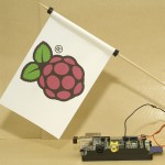
After the recent call for items for the demo table over at Raspberry Pi HQ, I thought I’d send over a flag-waving set. It’s not a product for sale, but it’s one of the most eye-catching and memorable Raspberry Pi demos I’ve made. People mention it more than any of the others when I don’t take it along to Jams. There’s a video, at the end of the page, showing three Pis all waving flags together (based on three different drive systems).
Making the flag
So I set about making a flag. It’s pretty easy. You need to print your logo twice on a piece of paper in such a way that it can be folded over and glued together to make the flag.

Raspberry Pi flag logo graphic
You can have the same on both sides or different, depending on your needs. In this case I went for a nice clean Raspberry Pi logo on both sides. The actual size of the flag should be ~15cm long by ~10cm high, but the exact dimensions don’t much matter.

Raspberry Pi flag waving essentials
Previously I’d always been very careful to leave enough space at the “flagpole” end for the flag to rotate freely. But when I was pondering how to avoid it being crushed in the mail, I suddenly realised the solution was at hand. Enter stage left, the humble drinking straw. All you have to do is insert a length of plastic drinking straw, and that will ensure the flag can rotate freely (and also prevent crushing in transit).

flag with straw insert
The other little secret to free-rotating flaggage is the use of a small plastic ring to prevent the flag slipping down the pole. I use a terminal protector from a 9V PP3 battery. You can see one above and one below the flag in the photo of the whole demo.
The flagpole is a bamboo skewer of the sort used in cookery/barbecuing. The potentially tricky bit is that you need a way of linking this to the servo. Being a recovering radio-controlled plane enthusiast, I happened to have wire, z-bend pliers and small diameter drill bits to-hand, to make a linkage like this…

control wire with z bend in
The only parts which are essential are the drill bits and wire.

Tiny modelling drill bits

Z-bend pliers – useful, not essential

2mm hole and 1mm hole roughly 2cm apart
You need a way of making a very small hole in your small diameter flagpole for the linkage wire and fulcrum to go through.

control wire fitted to servo horn
You’ll need a servo too. These can be had incredibly cheaply from sites like GiantShark.co.uk or HobbyKing.com. If you have an RC or robotics habit, you’ll probably have some lying around. ;)
A small servo is fine. I’m using a Dys 5g sub-micro servo (~£3 from Giantshark)

DYS sub-micro servo
Here’s how the linkage all fits together.

How the linkages all fit together
OK, but we still need to drive the servo somehow.
I’ve been using the ATMega on a Gertboard to-date. This gives lovely smooth movement and is still my favourite way, but I happened across a thread in the Pi forums which linked to an Adafruit blog tutorial by Simon Monk. It was all about how to control a servo directly with the Pi, using GPIO port 18 in pulse-width modulation (PWM) mode with Python and Occidentalis. “Awesome – that’s exactly what I need.” I thought to myself. So I flashed an SD card with Occidentalis 0.2 – click here to download
And it was. It makes the flag waving demo much more compact (although it isn’t as smooth as the Gertboarded version). It can be done with just the servo, the battery box, 4 x AA batteries and wires – but you need to make sure you hook up the right connections to avoid damage.
- Servo signal wire to GPIO 18.
- Servo GND (brown or black) to Pi GND
- Battery negative to another Pi GND
- Battery positive to servo postive (usually red)

Circuit to drive servo directly from raspberry pi

Two GNDs and a PWM signal connection. (5V from battery only goes to the servo).
I’ve looked into making it less juddery, but it seems the servo pwm driver can only handle 1 degree increments. So if you have a Gertboard or other ATMega device, by all means use it (look at the sweep sketch for a good place to start). If you want a compact and portable setup, and don’t mind a little bit of judderiness, this is the one for you. (Software is found if you follow the two Adafruit links above).
You dont need a Pi or a servo, but…
Of course, you could use cams and gears and an ordinary motor with on-off control instead of a servo, but then you wouldn’t need a Pi either – and where’s the fun in that? ;) If you want to be a spoilsport, you can also wave a flag by hand. :-P
Very nice ! Congrats !
But what about the software part ?
The software is in the adafruit link – perhaps I’ll make that a bit clearer :)
Oh yes. Thx.
I’ll think I’ll try that experiment ! :-)
Thanks for the share
[…] the break, I got the chance to meet Eben, demonstrate and hand over the raspberry pi direct servo controlled flag-waving demo for the Raspberry Pi Foundation’s demo table. We managed a few words as well. I would have […]
Is it possible to power the servo from the GPIO pins directly? Would be good to do away with that additional battery box!
I’m afraid not. I mean it might work for a while, but I expect it would damage the Pi – particularly if you “stall” the servo, it’ll try to pull a high current and the Pi will either reset or die.
Battery box also doubles as a stand for the flag. The weight of the batteries helps it not to fall over.
Ah that’s a shame, thanks for the reply.
Can the battery box be completely replaced with a standard 5V power supply? I mean I guess not just the servo, but the Pi too is powered from batteries in your example. Could I power the Pi and the servo from a strong enough (maybe 5V 2A) power supply instead from batteries? Thanks!
Yes
Thank you!
[…] Описание туториала на https://raspi.tv. […]
[…] great Raspberry Pi flag automated waving projects shared at RasPi.tv. Follow the “Read More” link for further hands-on tutorials for how to create the […]
[…] Been tinkering, and followed a tutorial from https://raspi.tv/2013/how-to-make-your-own-raspberry-pi-flag-waving-demo […]
Hi Alex
First I would like to thank you for you helpful and informative posts. I thought you may be interested in a YouTube video that I have posted giving a short demo of the Raspberry Pi and Interface boards, Gertboard and Piface. This video was inspired by your similar demonstratiion video some time ago and I give full credit to you for this:
http://youtu.be/UVcrjsELqd8
Thanks again.
Colin.
Nice one Colin. I will tweet this to the world. :)
[…] http://learn.adafruit.com/adafruits-raspberry-pi-lesson-8-using-a-servo-motor https://raspi.tv/2013/how-to-make-your-own-raspberry-pi-flag-waving-demo […]
[…] Mike Brojak from DesignSpark, whose voice you can hear in the video, asked me to put together a Wii controller flag-waving demo (plus other bits) on their new PiGo board. You may remember catching a glimpse of it in the flag waving video I produced a few weeks ago? […]
where did i make the mistake? i set like in this photo https://raspi.tv/wp-content/uploads/2013/03/RasPi.TV-flag-servo_bb2.gif ….
without power of pi. but now my pi doesnt work :(((
My guess would be you accidentally sent 5 volts up port 18. (Or made another gross error which proved fatal). But in the absence of any details of your setup it’s completely impossible to tell. Even then, I wouldn’t have expected it to kill the whole Pi, just the affected ports.
The other possibility is that your Pi is OK, but your file system or power supply has gone bad. Have you tried another power supply and SD card?
http://imageshack.us/photo/my-images/197/7df.png/
when i set, i had a photo. i think it is a correct circuit. because i also look at this page for servo motor cable colors: http://www.micro4you.com/store/tower-pro-sg90-micro-servo.html
i think now i could accidentally touch some cables. do you think could it be ?
if i get a new r-pi, can i try again( i afraid :( because r-pi is 50$ in my country))
when i connect power supply, power led of r-pi is on for 5-6 seconds.
my power supply is for samsung phone and i am now using it. but i did not try another sd card
The photo isn’t quite clear enough to check the wiring for sure, but at least on the Pi end it looks like things are on the right ports.
Do try another card if you can. It could just be a corrupted OS.
You’d be very unlucky to kill your Pi just by shorting a couple of wires momentarily. It really is best to do wiring with it all powered off (although hardly anybody bothers).
Interface boards (like the Gertboard or Quick2Wire) are designed to protect your Pi from accidental wiring mistakes… the “raw pins” on P1 are unprotected and just connect straight to the CPU.
hi again. i set my circuit and also used the occidentalis v0.2 for pwm.
for PWM there must be sys/class/rpi-pwm/pwm0/ folder but i dont have. did you have a trouble like this?
http://imageshack.us/photo/my-images/824/oy2i.png/
No. I just followed the instructions on the Adafruit site blog tutorial I linked to in the article and it “just worked”.
So did you install the black raspberry http://learn.adafruit.com/adafruit-raspberry-pi-educational-linux-distro/occidentalis-v0-dot-2
does that mean changing the OS for my pi from Raspbian “wheezy” to another OS “black raspberry”
I connected everything but how can I tell the motor to turn on using python ?
can you please provide more of the code you used
All the code you need is in the “Simon Monk” adafruit link above. You’ll need to flash a new SD card with Occidentalis if you don’t want to overwrite Raspbian.
“to flash a new sd card with occidentalis” and “to overwrite raspbian”
are these different thing? i couldnt understand.
i cleaned the card and set occidentalis v0.2. but some of raspberrypis may not boot cause of ram type. and then it didnt boot. i found this helping page and made what Dirks say:
“1. If you have a spare SD card download the latest Wheezy from this site, put it on an SD card. Then immediately (card still inserted in PC) copy above files from the SD card to a save location.”
then it booted but my problem is waiting for me
this is the link: http://www.raspberrypi.org/phpBB3/viewtopic.php?t=43484&p=347797
No idea how to help you with that one I’m afraid.
Sounds like the “problem” here is that AdaFruit haven’t updated their Occidentalis distro with the latest ‘/boot’ files, and as a result it doesn’t work with all variations of RaspberryPi :-(
http://www.raspberrypi.org/archives/3534 has a bit more info.
You’ll either need to follow the instructions in the forum thread you linked to (I haven’t tried them myself, but they look about right) or you need to pester AdaFruit to release an updated version of their distro :-/
…I see that http://learn.adafruit.com/adafruit-raspberry-pi-educational-linux-distro/occidentalis-v0-dot-2 says it was released 11 months ago (blimey), and “This distribution is not compatible with Raspberry Pi’s that have ‘HYNIX’ RAM Chips! We are working on a new distro that will be better than ever and also support HYNIX, no ETA at this time.”
*sigh*
Yes. The key word is NEW. If you don’t want to write over your SD card(s) with raspbian on, you need to take a new/different/fresh SD card and put Occidentalis on it. That’s all I meant.
Great article – used all the information you have provided to build a Fish Feeder. Please read about it in my blog
http://automation-experiments.blogspot.com/2014/08/fireball-gets-personal-robot.html
Thanks – you helped me save my fish while I was on vacation :)
Raj
Excellent :)
is posible to connect all pins directly to gpio? no battery box. thanks.
Yes but you might fry your pi running an inductive load from the 5V rail.
[…] method I’ve used to control the servo is similar to RaspiTV’s Raspberry Pi flag waving post – although I opted for the version detailed in the Raspberry Pi cookbook over […]