This is part 2 in a series on WiringPi 2 for Python. The basics are covered in part 1 (click here). You should read that first if you haven’t already, as we build on it here in part 2.
Today we’ll cover three things…
1. Raspberry Pi board revision checking with WiringPi2 for Python
2. Using the Raspberry Pi’s internal pull-ups and pull-downs with WiringPi2 for Python
3. Using hardware PWM with WiringPi2 for Python
1. Checking your Raspberry Pi board revision number in WiringPi2
It’s quite useful to be able to check what version of the Raspberry Pi board you are running. Some of the GPIO ports differ between revisions. So if you can check which revision of Pi your program is running on, you can make sure that the port/pin numbers it uses are correct.
If you use wiringpi’s own pin numbers, this is taken care of for you. But if you use the BCM GPIO numbers or the physical P1 header pin numbers, this feature will be useful for you.
After your…
import wiringpi2 as wiringpi
Put…
wiringpi.piBoardRev()
or…
Pi_rev = wiringpi.piBoardRev()
Then you can use the outcome to decide your port/pin numbers.
2. Internal pull-ups and pull-downs
In the button circuit in part 1, we used resistors to “pull-down” the port. This gives it a “default” state of 0V (0, False).
Why are they necessary/useful?
If you have no pull-up or pull-down resistors attached to a port, its status is not clearly defined. It is “floating”. It is susceptible to random electromagnetic radiation from you, from any devices near or far and from the environment. Any wires attached to the GPIO ports act as antennae for this radiation (it’s mostly radio waves).
So imagine the situation where you have a motor with a propellor on it, or one which controls Granny’s stairlift, which is switched on or off by a GPIO port. If that port is susceptible to random changes of state, the propellor might spin when it shouldn’t and hurt someone. Or Granny might be sent back upstairs when she wants to be downstairs. It’s an out-of-control situation. You can easily get it under control by using pull-up or pull-down resistors, so that’s what we do.
What’s all this about internal ones then?
In our button circuit, we used resistors to pull down the voltage. This was to demonstrate the idea.
But, in fact, the Raspberry Pi has built-in pull-up and pull-down resistors which can be enabled in software. The i²c ports have permanent, hardware pull-ups), but all the rest can be set/unset in software. This means we can eliminate our pull-down resistors for the button – as long as we enable the internal ones. (The circuit will still function without either, but may be unreliable.)
Activating internal pull-ups and pull-downs with WiringPi
WiringPi enables you do that. Having initialised WiringPi and set the port(s) to input or output, as we did in part 1, you need one of the following commands…
- Activate pull-up
wiringpi.pullUpDnControl(pin_or_port_num, 2) - Activate pull-down
wiringpi.pullUpDnControl(pin_or_port_num, 1) - Deactivate both pull-up and pull-down
wiringpi.pullUpDnControl(pin_or_port_num, 0)
Here’s an example where we set port 25 for input with pull-down enabled…
# GPIO port numbers
import wiringpi2 as wiringpi                    # load wiringpi2
wiringpi.wiringPiSetupGpio()                    # set up GPIO numbering
wiringpi.pinMode(25, 0)                         # sets GPIO 25 to input mode
wiringpi.pullUpDnControl(25, 1)                 # set pull-down
How does that apply to our ‘one input one output’ program?
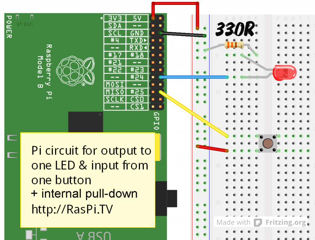
We’ll need to change the button led circuit first, to this (you could also just remove the 10k resistor to GND from the previous circuit)…
…and then, once you’ve done that, you need to insert a new line after line 7
wiringpi.pullUpDnControl(25, 1) # set pull-down
to enable the pull-down on the button port (25).
The whole program should then look like this…
import wiringpi2 as wiringpi
from time import sleep       # allows us a time delay
wiringpi.wiringPiSetupGpio()
wiringpi.pinMode(24, 1)      # sets GPIO 24 to output
wiringpi.digitalWrite(24, 0) # sets port 24 to 0 (0V, off)

wiringpi.pinMode(25, 0)                  # sets GPIO 25 to input
wiringpi.pullUpDnControl(25, 1)          # set pull-down

try:
    while True:
        if wiringpi.digitalRead(25):     # If button on GPIO25 pressed
            wiringpi.digitalWrite(24, 1) # switch on LED. Sets port 24 to 1 (3V3, on)
        else:
            wiringpi.digitalWrite(24, 0) # switch off LED. Sets port 24 to 0 (0V, off)
        sleep(0.05)                      # delay 0.05s

finally:                                 # when you CTRL+C exit, we clean up
    wiringpi.digitalWrite(24, 0)         # sets port 24 to 0 (0V, off)
    wiringpi.pinMode(24, 0)              # sets GPIO 24 back to input Mode
    # GPIO 25 is already an input, so no need to change anything
As you’ll see, if you try it out, it works just the same as the previous version.
That was fun, but now let’s do something we can’t yet do with the other Python GPIO packages out there…
3. Now Some Hardware PWM
Pulse-width modulation (PWM) is switching things on and off lots of times very quickly. It’s very useful for controlling things like motor speeds, led brightness, servo positions and a whole host of other things.
The Raspberry Pi has a hardware PWM port, which it shares with the 3.5mm audio output. If not using this audio output, you can use the hardware PWM port (GPIO18) on P1 header pin 12 or WiringPi pin 1.
To do that, you need to set up wiringpi and the set GPIO18 for alternative function (2)
import wiringpi2 as wiringpi

# If using BCM GPIO numbers
wiringpi.wiringPiSetupGpio()
wiringpi.pinMode(18,2)      # pwm only works on GPIO port 18
wiringpi.pwmWrite(18, 0)    # duty cycle between 0 and 1024. 0 = off, 1024 = fully on

# OR, using wiringpi numbers
wiringpi.wiringPiSetup()
wiringpi.pinMode(1,2)      # pwm only works on wiringpi pin 1
wiringpi.pwmWrite(1, 0)    # duty cycle between 0 and 1024. 0 = off, 1024 = fully on

# OR, using P1 header pin numbers
wiringpi.wiringPiSetupPhys()
wiringpi.pinMode(12,2)      # pwm only works on P1 header pin 12
wiringpi.pwmWrite(12, 0)    # duty cycle between 0 and 1024. 0 = off, 1024 = fully on
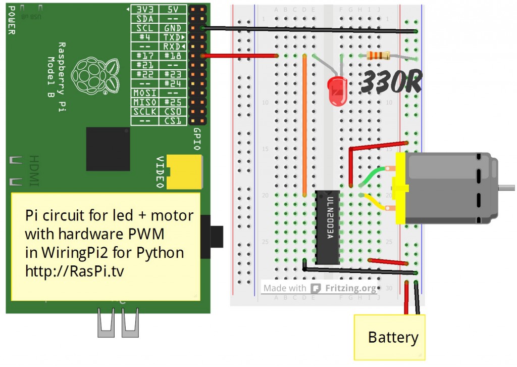
Why the Darlington Array chip?
You don’t need it at all for the led! It’s for the motor. Most motors need to run at a higher voltage than the Pi’s 3.3V offers, and a higher current than the GPIO ports can cope with. So we need a way of being able to switch a higher voltage with the 3V3 from a GPIO port. The ULN2003 is seven pairs of transistors that allow this switching in a safe way. You could just use a standard transistor, but this chip only costs ~30 pence or 50 cents so why not have the capability of switching 7 things at once – you don’t have to use them all?
The other nice thing this chip does is protect your Pi’s GPIO port from the voltage spike that can occur when an inductive load (a relay, solenoid, motor etc.) is switched off. It has built-in freewheeling diodes that give the required protection – all for much less than the cost of the separate parts. So in my opinion it would be rude not to use one. :)
You can get dedicated H-bridge motor control chips that will give you bidirectional motor control. But for this experiment I wanted to keep things simple and feed the motor raw PWM.
#!/usr/bin/env python2.7
# script by Alex Eames https://raspi.tv

import wiringpi2 as wiringpi
from time import sleep
wiringpi.wiringPiSetupGpio()
wiringpi.pinMode(18,2)      # hardware pwm only works on GPIO port 18
wiringpi.pwmWrite(18,0)     # duty cycle between 0 and 1024
                            # 0 = off and 1024 = constantly on

pause_time = 0.002          # you can change this to slow down/speed up

try:
    while True:
        for i in range(0,1025):         # 1025 because it stops at 1024
            wiringpi.pwmWrite(18,i)
            sleep(pause_time)
        for i in range(1024,-1,-1):     # from 1024 to zero in steps of -1
            wiringpi.pwmWrite(18,i)
            sleep(pause_time)

finally:
    wiringpi.pwmWrite(18,0)             # switch PWM output to 0
    wiringpi.pinMode(18,0)              # GPIO18 to input
This program cycles the led (and motor, if you connect one) from fully off to fully on and 1023 steps in between over a period of about 2 seconds.
As I found out when I wrote the motor demo program for the Gertboard, hardware PWM is superior to software PWM. You get more precise control. For example, hardware PWM can control servos without jitter, but soft PWM (even when written well) is not as good.
That’s about it for today. You might be surprised to realise that almost everything we’ve done so far could be done in wiringpi version 1. Next time we’ll have a look at some of the new and exciting stuff Gordon’s cooked up for us in version 2. :)
What we’ve covered so far
Part 1
Part 2


More pedanticism… ;-)
The I2C pullups are actually using physical resistors on the Pi’s PCB (R1 and R2, both 1.8kilohm) – they’re not internal pullups that can be deactivated in software.
The Pi (the BCM2835 chip) actually has two hardware PWM channels – one used by default for right analogue audio and one used by default for left analogue audio. But only the first PWM channel (PWM0, used for the right analogue audio channel) is also available as an alternative function on one of the P1 header pins.
More detailed info at http://elinux.org/RPi_Hardware#Schematic_.2F_Layout and http://elinux.org/RPi_Low-level_peripherals and http://elinux.org/RPi_BCM2835_GPIOs :)
I know the i2c resistors are hardware & permanent. I guess that part could be worded better to avoid ambiguity or just general lack of precision.
You say:- “The i²c ports have these permanently enabled (as pull-ups), “. That is not quite right, these lines have a strong external pull up resistor fitted on the Pi’s board which over rides anything you do with the internal pulling resistors.
Thanks Mike. Will amend :)
I see that the base wiringPi library, written in C now has support for software PWM on any GPIO pin. Does anyone know if this has been implemented in the python wrapper library? and if so how does one initialise and implement it?
I’ve never tried it either. I believe WiringPi 3 will be out very soon for the B+. When it is, we should badger Phil @Gadgetoid Howard to make it work. :)
It looks like on the B+ the external pull-ups are R23 and R24. They should be easy to remove with a soldering iron. Or even easier to remove with a pair of soldering irons or better yet, soldering tweezers.
I have been reading and testing this, and I have a question I wanted to ask you and I hope you don’t find this weird (I apologize if so!).
does wiringpi.piBoardRev() give the same result as GPIO.RPI_REVISION? Because I got a 2 instead of 3, if they should give the same answer. And the raspberry is the model B+.
Also when I use GPIO.RPI_INFO in Python I get this:
{‘P1_REVISION’: 3, ‘RAM’: ‘Unknown’, ‘REVISION’: ‘0010’, ‘TYPE’: ‘Unknown’, ‘PROCESSOR’: ‘Unknown’, ‘MANUFACTURER’:’Unknown’}
so it should be fine, shouldn’t it? But I’m confused because of the wiringpi part.
if you could help me here, I would really appreciate it.
thanks in advance!
WiringPi and RPi.GPIO are entirely separate projects, and you shouldn’t expect them to work in the same way, or return the same results.
IMHO to avoid confusion you’d be best off just sticking to one of them, rather than trying to mix the two; at least until you’re more familiar with things.
Ok, thank you AndrewS! I will use then, RPi.GPIO. I will be using this as a pulse counter. Is there any problem with using RPi.GPIO?
I mean that’s why I also installed wiringpi, in case I needed it.
thank you again for the quick answer!
I’ve personally not used either library in great depth(*), but I _suspect_ in terms of the GPIO functionality offered, there’s probably very little difference between them. There’s obviously only so much the Pi’s GPIO pins can be configured to do, and both RPi.GPIO and WiringPi seem to be relatively mature projects.
Steer clear of Quick2Wire (yet another Pi GPIO library) as that’s been abandoned.
(*) so all the usual disclaimers apply ;-)
Ok, thank you so mucho for your help! I will stick with the RPi.GPIO one then :)
The only real difference is that wiringpi offers hardware pwm on gpio 18 and has built-in functionality for port expander chips.
Thanks for the hardware pwm tutorial. I’d been reading http://wiringpi.com/reference/raspberry-pi-specifics/ and didn’t see any function for setting the duty cycle. Your use of pwmWrite() is what I’ve been looking for. I’m using Perl, but the same thing applies.