Over the last couple of weeks the pace of development for Python programmers who like to dabble in GPIO has gone up a gear. Both main GPIO systems for Python on the Raspberry Pi have been getting some enhancements.
RPi.GPIO, now at version 0.5.2a, has interrupts and threaded callback capability. You will probably have seen my three recent posts showing how to use those.
WiringPi for Python version 2 is in Beta testing. I discovered two bugs while I was trying it out. Both of those have been squashed. One by Gordon “Drogon” Henderson in the C source code and another by Phil “Gadgetoid” Howard in the Python install script. There’s a lot more stuff to test, but that’s not what I’m writing about today, so I’ll save that for a future post. Suffice it to say that the Python Gertboard software all works with WiringPi2 (at least it will when I release it soon with very minor tweaks).
RPi.GPIO PWM slipped in almost under the radar
As well as breaking my interrupt examples – now fixed :-P adding further enhancements to the interrupt facility, e.g. incorporating debounce code, Ben Croston has also added software PWM to RPi.GPIO (0.5.2a onwards).
So what? Why would I care about PWM?
It’s kind of useful. Let’s back up for a minute in case anyone doesn’t know what it is/does. PWM is pulse-width modulation. Put simply, this is a signal that is switched between on and off, usually rather quickly.
Do you remember when you were a kid, how you sometimes flicked the light switch on and off repeatedly, really quickly, to see what would happen? And you were told not to do it in case something bad happened (and it never did)? That was crude PWM.
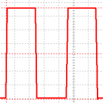
It’s a “square” waveform (on or off most of the time) and looks something like this…

A typical PWM “square” waveform
It’s used for controlling a variety of devices – motor speed, servo* positions and other things. You can even use PWM to vary the brightness of leds by switching them on and off at varying frequency and duration.
There are two important parameters that determine PWM…
- Frequency
- Duty cycle
Frequency
Frequency, in Hertz (Hz) is the number of times per second that a pulse is generated. This counts from the start of one pulse to the start of the next. i.e. from when the pulse starts to rise, to the next time it starts to rise. So it includes all the “on” time and “off” time and “in between” time for one complete wave cycle.
Duty Cycle
Duty cycle is the percentage of time between pulses that the signal is “high” or “On”. So if you have a frequency of 50 Hz and a duty cycle of 50%, it means that every 1/50th (0.02) of a second a new pulse starts and that pulse is switched off half way through that time period (after 1/100th or 0.01s).
Examples…
Frequency 50 Hz, duty cycle 50%.
This gives a pulse 50 times per second (or every 0.02 seconds if you prefer). During each 0.02 second time period, the port will be “High” (3.3V) half the time and “Low” (0V) the other half (ignoring transition time). The oscilloscope trace looks like this…

50 Hertz with 50% duty cycle
…you can easily see that the signal is high (3.3V or 3V3) half of the time. If you don’t have an oscilloscope, a multimeter will let you measure the duty cycle if you set it on Volts. 50% duty cycle should read 50% of 3.3 Volts = 1.65V, although it might fluctuate a bit.
Frequency 50 Hz, duty cycle 80%.
This one has a duty cycle of 80%, so the 3V3 pulse is “High” 80% of the time and the average overall voltage delivered is 2.64V (80% of 3.3V).

50 Hz with 80% duty cycle
If duty cycle is 100 or 0, frequency becomes irrelevant as the signal is either completely on or completely off.
Now let’s see how to control this with Python and RPi.GPIO
Requires RPi.GPIO 0.5.2a or higher
The following code contains all the elements you need to be able to control PWM on any available GPIO port on the Pi. The best way to see how it all works is in a live Python environment. To get there, open a terminal window and type…
sudo python
then you can try out the code interactively, as you will see in the video. If you want to measure the output, you’ll need to attach an oscilloscope or multimeter to your chosen GPIO port (25 in my case) and GND like this…

Scope probe to GPIO 25 and GND
Then type out or copy across (if logged in by ssh) snippets of code into the live python environment to see what they do. When you’re done, don’t forget to cleanup with GPIO.cleanup(), then hit CTRL+Z to exit the Python live environment. If any of that is unclear, you can see what I mean in the video. :)
# Don't try to run this as a script or it will all be over very quickly
# it won't do any harm though.
# these are all the elements you need to control PWM on 'normal' GPIO ports
# with RPi.GPIO - requires RPi.GPIO 0.5.2a or higher

import RPi.GPIO as GPIO # always needed with RPi.GPIO

GPIO.setmode(GPIO.BCM)  # choose BCM or BOARD numbering schemes. I use BCM

GPIO.setup(25, GPIO.OUT)# set GPIO 25 as an output. You can use any GPIO port

p = GPIO.PWM(25, 50)    # create an object p for PWM on port 25 at 50 Hertz
                        # you can have more than one of these, but they need
                        # different names for each port
                        # e.g. p1, p2, motor, servo1 etc.

p.start(50)             # start the PWM on 50 percent duty cycle
                        # duty cycle value can be 0.0 to 100.0%, floats are OK

p.ChangeDutyCycle(90)   # change the duty cycle to 90%

p.ChangeFrequency(100)  # change the frequency to 100 Hz (floats also work)
                        # e.g. 100.5, 5.2

p.stop()                # stop the PWM output

GPIO.cleanup()          # when your program exits, tidy up after yourself
I scoped it for you
Many people won’t have an oscilloscope, so I made a little video using a live Python environment. This shows the scope trace – what happens to the PWM signal – when we change different parameters in Python.
That was the basics, what next?
So that was the basics of how to use the new PWM facility in RPi.GPIO (0.5.2a onwards). I will write another article with some more complex program controlled PWM operations in. And perhaps we’ll get it controlling a motor or dimming leds or something? Watch this space.
The Official RPi.GPIO PWM documentation is here if you wish to press on ahead.
___________________________-
* Software PWM in RPi.GPIO doesn’t seem to be able to control servos as they require very precise PWM timings. More on that in the next article.
RasPiO® GPIO Reference Aids
Our sister site RasPiO has three really useful reference products for Raspberry Pi GPIO work...
Hi Alex. Auspicious timing. I’ve been using ServoBlaster but it conflicts with the camera module. Is there an easy way to make sure RPi.GPIO is the latest version? Or is it a wget and do-it-yourself jobby?
You can check in a live python environment
sudo pythonimport RPi.GPIO as GPIO
GPIO.VERSION
CTRL+Z to exit
Update using
sudo apt-get updatesudo apt-get dist-upgrade
but that will upgrade everything and might take an hour if you haven’t upgraded lately.
or go back to the interrupts tutorial pt3 and get the link directly to Ben’s google repo
http://code.google.com/p/raspberry-gpio-python/downloads/list
For servos you need 50 Hz PWM with pulses 1ms = 0 degrees, 2ms = 180 degrees. I haven’t tried them with this yet, but it’s on the to do list. :)
I suppose 1ms ~ duty cycle 0.1%, 2ms ~ 0.2%
You know I’m going to have to try it now don’t you? ;)
Actually it didn’t work very well Mike. Maybe it’s not up to the job for such short pulses?
When you say it didn’t work very well… what do you mean? Did it work at all?
Still investigating, but no, it’s unusable. Scoping it at the moment alongside a servo tester (which is a 50Hz signal generator variable, 0.9-2.1 ms) and the soft PWM is all over the place.
It’ll be OK for motor control etc, leds, but not precise enough for the short pulses required by servos.
I didn’t know that until you made me try it. :-P
can you use your Arduino nano for that?
Actually, scoping it, I’ve managed to get a trace that looks like the servo driver output. Parameters Frequency 50.6 Hz, duty cycle 4-10 %. That might be your usable range. Gonna try it on a servo now. It’s fairly stable and just might do the trick. :)
Update – nah – too jittery. Not for servos. It does move them, but not stable. It was always going to be a big ask of software PWM in python.
Guess I’d better stick to my ‘C’ code then. Ho-hum.
Great article, thanks! I might try to make a dimmer for an LED.
Thanks Krystal. Nice blog you’ve got there too. I would think a good starting frequency for led dimming might be about 100-500 Hz and the duty cycle should take care of the rest. I’ll probably cover something like that in the next blog in a few days. :-)
Hi Alex. Appreciate the great tutorials. The incorporation of PWM into the RPi.GPIO library would’ve slipped under my nose too if hadn’t run into this :)
Question I have is whether or not you ever did any testing with frequencies for fading LEDs? I have done some testing and I am getting quite a bit of flickering for all frequencies ranging from 100 – 500Hz as you suggested above. I was using pi-blaster previously for PWM and the fading is perfectly smooth with it (no flickering); not sure I can make the switch if I can’t resolve the flickering issues.
Any suggestions? Thanks for your help!
Hmm – I hadn’t noticed any flickering issues when I did the second part. There’s a video there too where you can see the leds up close and personal. https://raspi.tv/2013/how-to-use-soft-pwm-in-rpi-gpio-pt-2-led-dimming-and-motor-speed-control
What else is going on in your script? It may be that something else is “interrupting” the process? Or something else going on in the background on your Pi?
The script really isn’t doing much. I have 2x 30 LED/per strip LEDs connected to the GPIO pins listed in gpioPinsList. Create objects for each, then fade. Here’s the code:
import RPi.GPIO as GPIO

import time
#PWM frequency
HZ = 100
FADESPEED = 0.002
GPIO.setmode(GPIO.BCM)
gpioPinsList = [["r1",18],["g1",23],["b1",25],["r2",17],["g2",22],["b2",24]]
gpioPinsObjs = []
#setup GPIO pins as outputs and create PWM objects for each
for i in range(len(gpioPinsList)):
GPIO.setup(gpioPinsList[i][1], GPIO.OUT)
gpioPinsObjs.append(GPIO.PWM(gpioPinsList[i][1], HZ))
try:
for j in range(len(gpioPinsList)):
gpioPinsObjs[j].start(100)
time.sleep(FADESPEED)
while True:
#fade in
for i in range(101):
for j in range(len(gpioPinsList)):

    gpioPinsObjs[j].ChangeDutyCycle(0 + i)
time.sleep(FADESPEED)
#fade out
for i in range(101):
for j in range(len(gpioPinsList)):
gpioPinsObjs[j].ChangeDutyCycle(100 - i)
time.sleep(FADESPEED)
except:
GPIO.cleanup()
pass
As I mentioned the transitions are completely smooth when I use pi-blaster instead which kind of rules out a background process interfering with the GPIO writes. The only thing I can think of is I am not using the library properly or missing some setting?
Thanks again
Maybe you’ve just pushed it past its useful limits?
I will run some tests by just fading a single pin instead of trying to do all 6. I’ll let you know how the testing goes. That is what you are referring to correct? Too many pin writes?
Yep. It’s got to be worth a try, although I think I have had six working at once before. I’m sorry I haven’t got time to dig into your code at the moment, I’m still working.
No worries. I am still working myself ;)
I gave it a shot with the exact code you have posted for the LED fading that you have on your other blog post; only writing to two pins. I still see the problem at the fadespeed 0.02. However when I speed the fadespeed up too say 0.002 there is negligible jitter. I’m thinking maybe the fading happens so quickly that you can’t really tell. Not sure. I think I will stick with pi-blaster until I can find time to figure out some other tests for it. Thanks for all your help!
I haven’t experimented with PWM or LED fading myself, but I just thought I’d chip in with a quick Python tip.
Instead of doing:
for j in range(len(gpioPinsList)):gpioPinsObjs[j].ChangeDutyCycle(0 + i)
you could just do:
for pinObj in gpioPinsObjs:pinObj.ChangeDutyCycle(0 + i)
which eliminates the use of both the len() and range() functions (which may help for tightly-optimised loops).
Wow. I really bloated that one didn’t I :)
I ended up trying another script that was much simpler than the one I posted earlier (without any of the range or Len functions) but unfortunately was still experiencing the same sketchiness with the LEDs.
Much appreciate your suggestions though AndrewS! I will be using this to update some other unrelated areas of my code.
Hey, I’d recommend using +d instead of +z. +z sends python to the background. This is of course useful if you want to reuse the process with “fg”. But most of the time you want to quit python and that is done with +d.
Thanks I’ll try that next time. I already use that one to exit screen. Looked it up, it’s the EOF/EOT signal in ASCII. CTRL+Z is apparently what is used in Windows, which must be where I picked it up. I started learning Python on Windows before I had a Pi. :) By the way, your comment was filtered into the spam. I rarely check there and usually bulk delete, so I’m lucky I did on this occasion. :)
Have you looked at http://pythonhosted.org/RPIO/ ? It claims to be a “drop-in replacement for RPi.GPIO” but it’s PWM usage seems to be a bit different to RPi.GPIO, and it seems to have a dedicated Servo module.
I’ve been following the thread on it in the forums, but not tried it yet. I gather it uses RPi.GPIO and builds on it. But the PWM scope traces Chris posted looked very “square wave” indeed. :)
Arghh – just realised I’ve been missing the “Notify me of follow-up comments by email” tickbox :-(
Could it be moved above the “Submit Comment” button please?
I’ll look into it Andrew. Not really sure which file in wordpress to edit, but I’ll google it and see. It might be my theme though.
In the meantime, is there any way to view a bigger list of “Recent Comments” somewhere than just the 5 displayed in the box on the right? (RSS or something?)
https://raspi.tv/comments/feed
*slaps forehead* :silly:
It’s the smileys plugin. Seems to insert itself between the submit button and subs boxes. I haven’t found the file to edit yet, but I can deactivate the plugin (I kind of like it though). :p
TBH when I first saw the “Click to Insert Smiley” I thought it was one of those annoying banner ads you get sometimes ;-)
No advertising on this site. I’m not going to say never, but if I ever do accept any it will be relevant and not served up by Amazon or Google. I’m trying to build a decent site here.
[…] interfacing, python programming, Raspberry Pi Hardware Add comments Apr 212013 In part 1 of this series, we looked at the basic commands for using software pulse-width modulation … In this article we’ll get a bit more hands-on and into some practical applications for it. […]
Thanks for posting this info, I found it very useful indeed. I do have a question though, if you could help? I built a pulsing LED python script using this and it works like a dream. However if started via /etc/rc.local and subsequent python scripts are being executed via sub processes i find the pulse to be highly erratic.
I have tried throttling the individual python processes with renice, to no avail. Weirdly though if I kill the rc.local launched python process and restart within an interactive shell, no erratic behaviour.
I wondered if there is some kind if implicit PWM throttling as a non shell launched python instance.
I am at a loss tbh.
That does sound a bit odd. It must be something to do with prioritisation of access to the CPU, but that’s “well above my paygrade” i.e. I wouldn’t know where to begin with that one. Ben might be able to throw some light on it, if you ask in the Python section on the Pi forums.
[…] other day that I’ve published some fairly advanced RPi.GPIO tutorials, (e.g. interrupts and PWM) but not done anything more basic, apart from the Gertboard examples. So here’s an attempt to […]
[…] PWM controller that can be used to control the brightness of the LEDs (0 = OFF, 255 = Fully ON). (More on PWM here) PiGlow in […]
is there any way to put a “sweep” function into the pwm code. i mean a function that starts at a given frequency eg 50hz and sweeps up to and stops at eg 5kHz at a given increment(eg 2 hz per step)?
Sounds like you’d probably need to add an enhancement request to http://code.google.com/p/raspberry-gpio-python/issues/list
Guys, so can i now the phyton script for adjusting the duty cycle of square waves generated from GPIO pin of Rpi…
p.ChangeDutyCycle(90)
I’m not sure what it is you’re asking??
Guys, my question is that i designed a webpage containing 4 buttons( for controlling speed of fan at 4 levels). Now i also wrote a code in python on determining the duty cycle if the user presses button 1,2,3 or 4. My actual query is that what should i do, if python want to interpret the command given in my webpage. Clearly speaking, if i press 1 in webpage i should get a command invoking the code in python and it should generate appropriate pulse width. So, i am asking about how to interface the webpage command within raspberry pi.
Well, that’s quite a different question to what you were first asking ;-)
I’ve never looked into web-control of the Pi myself, but I’ve seen other people mention https://code.google.com/p/webiopi/
For such a generic question, you’d probably get better help at http://www.raspberrypi.org/forums/ than in the comments section of Alex’s blog…
Yes PWM does work very well in my case with servo. However if I unplug the power the code will still work. Is there any possible way to check if the device is plugged and receiving the signal?
No. Servos are ‘output only’ devices, so from the Raspberry Pi there’s no way to detect if they’re working.
(Unless you add some kind of external rotary encoder to the servo, and read that from the Pi)
can we use this code for the for the brush-less motor?
No. You need an ESC.