
I’ve recently been working on a new board called the RasPiO® duino. You might guess from the name that it’s a bit Arduino-like, and it is. I’m currently on iteration 5 and there’s going to be at least one more before production. All iterations have worked, but I keep getting ideas and suggestions from my beta testers (and myself) that I want to include.

RasPiO duino rev 3 prototype
But the board is not really what today’s post is about. I want a way of preventing the water inlet pipe freezing in the basement of our house in Poland. In a very harsh winter, the temperature in the basement, where the water inlet is, can get close to zero. That’s bad because if the water in our inlet pipe freezes, it could burst. The central heating water is drained and the system is empty, but there’s a 3 foot pipe sticking up from the ground before it gets to the inlet valve. That pipe and the inlet valve are what I want to protect.
I know there are ‘proper’ solutions for this, but where’s the fun in that? I want to make my own.
Here’s a video about it…
Read Sensors, Control Relays
What I need is a way of safely and gently heating the surrounding area, or the pipe itself, if/when the pipe temperature gets too low. That sounds like a job for a small, autonomous, low-power device that can read temperature sensors and switch relays.
An arduino type device is ideal for this because, if there’s a power cut, it’ll ‘just work’ when the power is restored. You could use a Pi, but there is still a chance of SD card corruption, so it’s a bit less bullet-proof. I haven’t had an SD card corruption for over a year, but I know other people have. Liz mentioned, on the Foundation’s blog last week, an SD card corrupting because someone removed the power lead.
Let’s Use a RasPiO® duino
So, since I’ve got the RasPiO® duino to play with, I thought I’d use that and a little relay board, some TMP-36 sensors and a 12V Halogen bulb or two. And, because we all love LEDs, let’s have some of those too, as indicators.
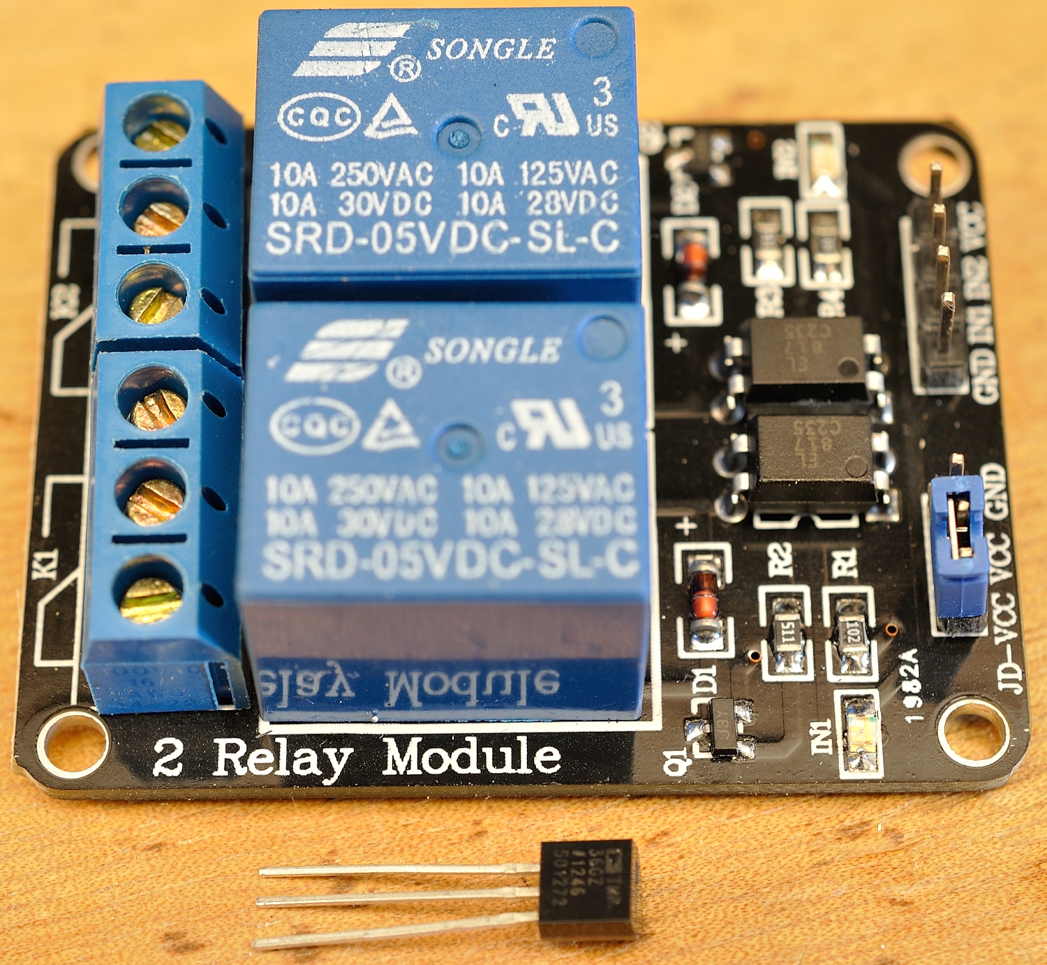
Relay board and TMP-36 sensor
The nice thing about this setup is that you can program the RasPiO® duino with the Pi, and then detach it, if you want to, for autonomous use.
How Will It Work?
All I really want here is a relay to switch on a lamp to provide a little heat if the pipe temperature gets too close to freezing, and then switch off again when it warms up a couple of degrees. The duino is perfect for that.
Such a system will need some redundancy in case parts of the system fail. There are two relays on the relay board, so I may as well use them both (with a bulb each) in case one fails. I’ll use at least two temperature sensors and have each one controlling a lamp. There are 6 analog channels on the ATMega 328P-PU chip, so we could use up to 6 analog sensors.
Here’s what the whole setup looks like in prototype…
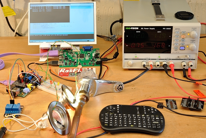
The whole RasPiO duino temperature control system
It Needs Smoothing and Anti-Oscillation
Two problems I encountered along the way were…
- Temperature measurement instability
- Oscillation – too frequent switching on and off of the heating circuit(s)
I tackled measurement instability on several fronts…
- Stabilised the TMP-36 sensors with a 0.1uF capacitor
- For every measurement, read the ADC 6 times and ignore the first reading for each set.
- Keep the last five results (each one itself an average of 5 readings) in an array to smooth the results and reduce the effect of sudden large swings or outliers
- Only switch on the heating circuit relays in response to the smoothed (moving average) results
Oscillation was dealt with by forcing the heating circuit(s) to stay on for 30 cycles once switched on. The idea here is that, since each cycle is ~1s, the heating lamp (or whatever I end up using) will not be switched on and off rapidly, but will always stay on for a minimum of 30s.
Arduino Code
Here’s the code for the ATMega chip. A lot of the code is duplicated. I expect there’s a ‘tighter’ way of doing it, but I’m no expert at Arduino code (which I’m told is pretty much the same as C++). I had to learn some new stuff to get this far…
//
const int numReadings = 5; // number of readings in moving average array

//TMP36 Pin Variables
int sensorPin0 = 0; //= A0 analog pin 0. TMP36's Vout (sense) pin is connected to A0
int sensorPin1 = 1;

int index = 0;
int thisReading = 0;
int reading = 0;

int readingsT1[numReadings]; // number of results to store in moving average array
int totalT1 = 0;
float averageT1 = 0;
int cyclesT1 = 0;

int readingsT2[numReadings];
int totalT2 = 0;
float averageT2 = 0;
int cyclesT2 = 0;

int LEDpin1 = 9;
int LEDpin2 = 10;
int LEDbrightness;
int LEDbrightness2;
int relaypin1 = 4;
int relaypin2 = 3;

void setup()
{
  Serial.begin(9600); //Start the serial connection with the computer
                      //to view the result open the serial monitor
  pinMode(relaypin1, OUTPUT);
  pinMode(relaypin2, OUTPUT);
  digitalWrite(relaypin1,HIGH);  //HIGH is off for the relays
  digitalWrite(relaypin2,HIGH);

  for (int thisReading = 0; thisReading < numReadings; thisReading++)
  {
    readingsT1[thisReading] = 233; // set all values to 233 = 25 degrees C
    readingsT2[thisReading] = 233;
  }
}

void loop()
{
         //get digitised voltage reading from temperature sensor
    analogRead(sensorPin0);
    delay(20);
    reading = 0;
    for (int loop = 0; loop < 5; loop++)
    {                                         // read sensor 5 times
       reading += analogRead(sensorPin0);
       delay(20);
    }
    readingsT1[index] = reading / 5;  // average integer readings + amend array
    totalT1 = 0;
    for (int thisReading = 0; thisReading < numReadings; thisReading++)
       totalT1 = totalT1 + readingsT1[thisReading];
    averageT1 = totalT1 / numReadings;               // float average ADC readings
    averageT1 = averageT1 * 3.29 / 1023;             // convert to decimal voltage
    averageT1 = (averageT1 - 0.5) * 100;             // convert to temp in C

    float voltage = reading * 3.29 / 5.0;
    voltage /= 1023.0;

    reading = 1023 - reading;
    LEDbrightness = map(reading, 0, 1023, 0, 255);
    analogWrite(LEDpin1, LEDbrightness);

    Serial.print("ID1 ");Serial.print(voltage); Serial.print(" V ");
    float temperatureC = (voltage - 0.5) * 100;
    Serial.print(temperatureC); Serial.print(" C.  ");
    Serial.print(averageT1); Serial.print(" C.  Average ADC: ");
    Serial.println(readingsT1[index]);

    // if temp <=22 turn on heat and keep it on for 30 seconds/cycles
    if (averageT1 <= 22)
    {
       digitalWrite(relaypin1,LOW);
       cyclesT1 = 30;
    }

    // ensure 30 iterations, so heat stays on for 30 cycles (avoids oscillation)
    else if (cyclesT1 > 0)
    {
       cyclesT1 -= 1;
    }

    // switch off heat if >22 C AND cyclesT1 = 0
    else
    {
       digitalWrite(relaypin1,HIGH);
    }

// Now do it all again for sensor 2 and relay 2

    analogRead(sensorPin1);
    delay(20);
    reading = 0;
    for (int loop2 = 0; loop2 < 5; loop2++)
    {                                             // read sensor 5 times
       reading += analogRead(sensorPin1);
       delay(20);
    }

    readingsT2[index] = reading / 5;  // average integer readings + amend array
    totalT2 = 0;
    for (int thisReading = 0; thisReading < numReadings; thisReading++)
       totalT2 = totalT2 + readingsT2[thisReading];
    averageT2 = totalT2 / numReadings;               // float average ADC readings
    averageT2 = averageT2 * 3.29 / 1023;             // convert to decimal voltage
    averageT2 = (averageT2 - 0.5) * 100;             // convert to temp in C

    voltage = reading * 3.29 / 5.0;
    voltage /= 1024.0;

    reading = 1023 - reading;
    LEDbrightness2 = map(reading, 0, 1023, 0, 255);
    analogWrite(LEDpin2, LEDbrightness2);

    Serial.print("ID2 ");Serial.print(voltage); Serial.print(" V ");
    temperatureC = (voltage - 0.5) * 100;
    Serial.print(temperatureC); Serial.print(" C.  ");
    Serial.print(averageT2); Serial.print(" C.  Average ADC: ");
    Serial.println(readingsT2[index]);

    // if temp <=22 turn on heat and keep it on for 30 seconds/cycles
    if (averageT2 <= 22)
    {
       digitalWrite(relaypin2,LOW);
       cyclesT2 = 30;
    }

    // ensure 30 iterations, so heat stays on for 30 cycles
    else if (cyclesT2 > 0)
    {
       cyclesT2 -= 1;
    }

    // switch off heat if >22 C AND cyclesT2 = 0
    else
    {
       digitalWrite(relaypin2,HIGH);
    }

    delay(1000); //waiting a second

    index = index + 1;
    if (index >= numReadings)
       index = 0;
}
Python Code Runs on the Pi
There’s also a short Python script which runs on the Pi. This can be used to monitor what’s happening. It was absolutely essential while developing the arduino code, to be able to see what was happening. It reads and displays what the ATMega is writing to the serial port and does further smoothing on the results. There’s a bit of repetitive code that could probably be put into a function.
import serial, subprocess, sys
from time import sleep

def print_there(x, y, text):
    sys.stdout.write("\x1b7\x1b[%d;%df%s\x1b8" % (x, y, text))
    sys.stdout.flush()

correction_factor = 0  # 0 for none
correction_factor2 = 0  # 0 for none

subprocess.Popen("clear", shell=True)
degree = unichr(176)
first_time = True
first_time2 = True

while True:
    sport = serial.Serial("/dev/ttyAMA0", 9600, timeout=1)
    try:                                       # stops program failing if no serial data
        response = sport.readlines(None)[0:2]
        sport.close()
    except:
        sport.close()

    if not response:                           # stops program failing if no serial data
        print "no serial data read"
        sleep(0.5)
        continue                               # if no data, skip to top of loop and retry

    print_there(1,1,response[0])
    print_there(2,1,response[1])
    if response[0].startswith("ID1"):
        temp = (float(response[0].split()[3]) + correction_factor) #'%.2f' %
        if first_time:
            temp_list = [temp, temp, temp, temp, temp]
            first_time = False
        del temp_list[0]
        temp_list.append(temp)
                                 # makes a weighted moving average of last 5 readings
        smooth_temp = "%.1f" % round(float((temp_list[0] * 0.1) + (temp_list[1] * 0.15) + (temp_list[2] * 0.2) + (temp_list[3] * 0.25) + (temp_list[4] * 0.3)), 1)

        volts = float(response[0].split()[1])

        output1 = ''.join((" Sensor1: ",str(smooth_temp)," ",degree,"C   ",str(volts)," V"))
        print_there(3,3,output1)

    if response[1].startswith("ID2"):
        temp2 = (float(response[1].split()[3]) + correction_factor2) #'%.2f' %
        if first_time2:
            temp_list2 = [temp2, temp2, temp2, temp2, temp2]
            first_time2 = False
        del temp_list2[0]
        temp_list2.append(temp2)
                                 # makes a weighted moving average of last 5 readings
        smooth_temp2 = "%.1f" % round(float((temp_list2[0] * 0.1) + (temp_list2[1] * 0.15) + (temp_list2[2] * 0.2) + (temp_list2[3] * 0.25) + (temp_list2[4] * 0.3)), 1)

        volts2 = float(response[1].split()[1])

        output2 = ''.join((" Sensor2: ",str(smooth_temp2)," ",degree,"C   ",str(volts2)," V"))

        print_there(4,3,output2)
    sleep(2)
Use With or Without Pi
The system will work perfectly ‘off-pi’, but the Pi can be attached to give a real-time temperature readout using the serial ports. It could also be used to…
- log or tweet updates/alerts
- monitor remotely via internet
- or even to reprogram the duino
But I may not use a Pi once the duino board is programmed. I don’t have an ethernet port in the basement, and the wifi router is two very thick concrete floors away, on the first floor. We’ll see.
Don’t Use it for Mission-Critical Stuff
I did this for fun. I don’t know if it’s robust enough or even fit-for-purpose. If you have a really important system to control, you’d better not use this unless you know what you’re doing. For me, it was a fun learning exercise.
Alex I use a pair Ethernet/Mains 200Mb adapters from BT Shop abt £16 these get a Pi from a Garden Shed back to the house. Gave up using WiFi in a Victorian solid wallled house a long time ago. On a project I used 555 Time in Monostable mode to switch a 12v pump for an preset time from a Pi then looked at the results 10 minutes later. Sound like a nice little board. Terry R
Thanks Terry. The power line adaptor sounds like a good idea – except, I think the router and basement may be on different circuits. Not sure quite how it works over there. Good idea though. :)
Just bought some of these and tried them in the basement. They certainly work on one of the circuits down there, so I now have a way to escape the worst of the summer heat. Thanks for the idea (even if the Euro connector ones I bought locally were twice the price of the Amazon ones :( It’s still worth it.)
So you didn’t go with the old-skool “really long Ethernet cable running down the side of the stairs” solution? ;-)
That would have been a very ugly solution (we already have something similar for the TV aerial) and I would still have had to drill a hole in either a door or an 18 inch thick concrete floor. :)
Regarding the serial-header on the RasPiO duino – I’d still draw a separate line between 5V and GND to make it clear that the serial pins themself aren’t running at 5V ;-)
I only skimmed over the Arduino code but spotted at least one bug:
for (int thisReading = 0; thisReading < numReadings; thisReading++)
readingsT1[thisReading] = 233; // set all values to 233 = 25 degrees C
readingsT2[thisReading] = 233;
will set all elements of readingsT1 to 233, but only set the last element of readingsT2 to 233 (because of the missing braces).
Personally, I'd make readings a 2-dimensional array (eliminates duplicate code, and makes it easy to add extra sensors later!) with:
int readings[numSensors][numReadings];
and then initialise it with something like:
for (int thisSensor = 0; thisSensor < numSensors; thisSensor++)
{
for (int thisReading = 0; thisReading < numReadings; thisReading++)
{
readings[thisSensor][thisReading] = 233; // set all values to 233 = 25 degrees C
}
}
When there's only one enclosing line used with a for loop (or if statement) it's optional to use the braces (makes the code shorter), but including them anyway makes it easier to avoid bugs later ;-)
Maybe you could also print over the serial connection whether each relay is switched on or off?
Where you say "to get the voltage to a safe level" did you actually mean temperature?
You couldn’t possibly know this, but that serial header is deleted on rev 5 :) I needed the space and realised that all the pins are broken out elsewhere on the board anyway.
Thanks for the bug report. (I’ve changed the code, so if anyone copies it, it’ll be less buggy.)
Yes I mean voltage. As in I’m using 12 V halogens from PSU instead of mains powered bulbs at 240 VAC.
Last time I did relays with mains, I got crucified by the safety cops.
Ah, see what you mean now. But the way you’ve worded the article, sounds like the bulbs themselves are changing the voltage??
I’ve deleted the remark as it was part of a longer comment that had already been deleted, and, you’re right! It didn’t make much sense when orphaned. It brought nothing to the party, so it’s gone. :)
Alex They work on any mains cable circuit inside of the Mains Fuse box
Should be alright in theory, but you haven’t seen the wiring over there. The house isn’t even earthed. Although new houses are, this house was built in the 1970s in commie times (although we added the 1st floor 10 years ago – and no, that’s not earthed either.)
“The house isn’t even earthed.”
Just like in http://www.imdb.com/title/tt1049413/ ? Cool!
“and, you’re right!”
It happens occasionally ;-)
the units £16.97 a pair
AV200 200Mbps Mini Powerline Adapter Starter Kit
Thanks. I’ll have a look. Could do with ethernet in the garage here anyway :)
Oopsie. I appear to have ordered a pair ;)
I guess implementing something like a http://en.wikipedia.org/wiki/Schmitt_trigger in software would also be a way to eliminate the rapid on/off switching.
Hello Alex,
where in Poland do you live? Maybe you will find some time and visit RaspberryPi user group in Katowice?
My wife’s family come from the Zgierz area. We have a house in Zgierz, where we go in the school holidays. Katowice is a bit far, but who knows?
It’s only 200 km ;) You are always welcome
Alex Can I assume this board will be available at some point. I have been doing a project to water the wife’s tomato plant while we are away using a Raspberry Pi water valve and soil probes. Not far removed from what you are doing it would be good to have a computer that cannot crash on the job. To switch the solenoid valve I am using the GPIO to a 555 monostable into a 555 astable PCB this make sure the solenoid valve can only be fired once (on switch on) and not stay ON with water flowing.
As the name suggests, Alex’s board is simply a ‘respin’ of the Arduino
http://arduino.cc/en/Main/Products?from=Main.Hardware
And there’s also many many Ardiuno clones, any of which would be suitable for the job
http://playground.arduino.cc/Main/SimilarBoards#goArdComp
Or if you want something a bit closer integrated with the Pi and can’t wait for Alex’s RasPiO duino, you could take a look at Gertduino
http://www.raspberrypi.org/introducing-gertduino/
or Gertboard
http://www.raspberrypi.org/assembled-gertboards-available/
Choices, choices… ;-)
…and taking it to the extreme, there’s things like
http://www.raspberrypi.org/opensprinkler-pi/
I have a couple of rev 3 boards left. I could let you have one of those at a discount, and you could have it quite soon (since you’re in UK). I’ll send you an email to the email address you entered here.
[…] Alex Eames at RasPi.TV has invented a new board that plugs into the Raspberry Pi. Called a RasPiO duino, it’s programmable from the Pi and will also work away from the Pi providing it’s given a power source. He has a problem at his house over in Poland – the basement gets so cold that the water in an inlet pipe can freeze (and make the pipe burst). So, he’s used a combination of his new board, some relays and some heat lamps to Macgyver a solution together. There’s more detail and a video over on his blog. […]
Did you consider using hysteresis approach to avoid oscillation? This is the usual way to handle such situation. For example you turn heating on when temperature reaches 0 C or less, but when it is on, you don’t turn it off unless temperature reaches 2 C.
In any case, sensors should be placed in a way that heaters don’t have immediate impact on readouts.
Yes I did consider hysteresis approach. Coupled with a time limit, I think it would be better for a real-world situation.
Agreed about the sensor placement. They were done like that for quick prototyping and for the sake of the video. I probably wouldn’t use lightbulbs for the ‘real thing’ either, but some sort of thermal wire or heat collar. But the light bulbs make it nice and visual for the video. :)
You don’t have to use time limit if you have hysteresis with right thresholds. And yes, it works really well in real world indeed. I use it in monitoring servers temperature to avoid alert flickering.
Lightbulbs are pretty cool – almost no risk of short circuit, high heating efficiency (especially old type), you can make UFO like effects… ;-) I’d just put larger PCV pipe around the water pipe. Seal it. Place sensor at lowest point (consider a little bit of insulation[1]), heat source in the middle. Check how much time is needed to change temperature for 1-3 C, program the threshold. Voila.
[1] BTW is insulation exactly the same as isolation in English? Regarding cables or temperature.
Random google result: http://english.stackexchange.com/questions/51480/difference-in-meaning-in-insulation-vs-isolation
P.S. Hysteresis is what I was referring to earlier when talking about Schmitt triggers.
Thanks. Good ideas.
Insulation and isolation are not quite the same thing in English, but very similar.
I know it’s ‘izolacja’ for both in Polish. Father-in-law used to call insulating tape ‘izolacja’ instead of tasma izolacjyna. (He was a bit of a country type.)
Broadly speaking, insulation is about protecting/preventing movement of something, whereas isolation is separating something.
OK, got it. Make sense. I asked, because in Polish there is only one word (izolacja) for every case. First I thought that isolation refers to people (lack of contact), then that some American English vs British English is involved. Finally, I had no idea. Thank you for clarification.
Please let us know some results of real world tests. I wonder how long you need to light a bulb to change temperature.
@AndrewS Yes, now I noticed that Schmitt triggers are implementation of hysteresis in electronics.
I’m looking forward to using Nanpy rather than Firmata. You can then use the Arduino’s PWM pins and AtoD converters directly from Python with access to Arduino libraries.