The Pi Zero attracted a huge amount of attention, which is great for the educational mission of the Raspberry Pi Foundation. Whenever a new product is released, people air their opinions in the forums on what they would have liked it to have.
One of the most common “I wish it had”s was an ethernet port. There are reasons why ethernet was not included. The two most obvious ones are cost and board size (it would have almost doubled the size of the Zero)
So What’s To Be Done If You Need Ethernet?
Well the obvious solution would be to buy a B model Pi. B+ is fairly inexpensive these days, but also the Pi2 B has ethernet.
The other option, that we’re going to cover today, is to add an external ethernet port using the SPI pins on the Pi.
Some time ago I managed to kill the ethernet/usb hub chip on one of my model B Pis. I thought it was a gonner. With no USB or ethernet, the only way I could log into it was through the serial port. Then someone (I think it was Alex Bradbury) pointed out that you can add ethernet over SPI. I looked into it. There was a forum thread about it, where people had done this, so I bought a little ethernet board for Arduino. It has an ENC28J60 chip on it, an ethernet port, a 25 MHz crystal and some resistors and capacitors…
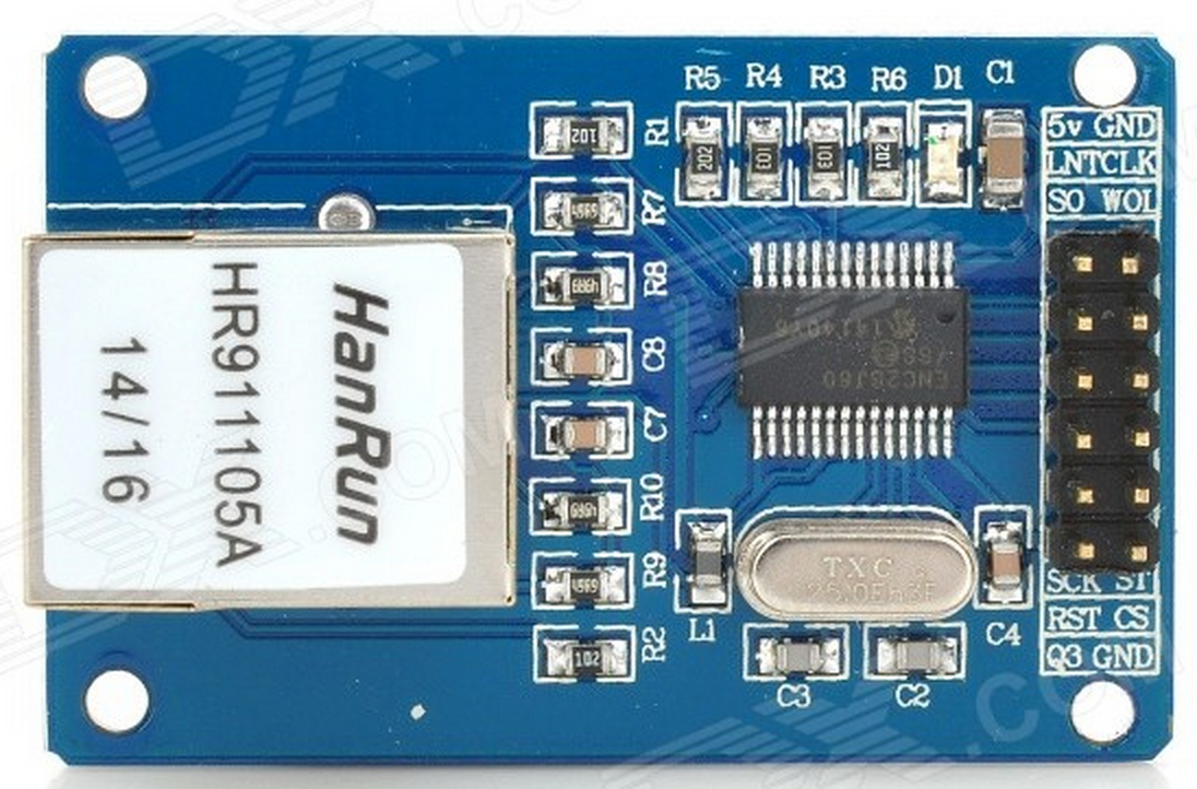
ENC28J60 based ethernet board
And Then It Sat In A Box
When it arrived I did a classic geek thing. I looked in the forum post again. It looked hard and a bit scary (nobody had RasPi.TVed the procedure) and I had other stuff to do. So it sat on my desk for a while and eventually went in my box of “Things I’ll get around to using one day – perhaps”. It’s been in that box for a while now.
But Then Came The Zero
Provoked by the mass of “I want an ethernet port on my Zero” comments, I decided it was time to have a go. Fortunately, in the meantime, a device-tree driver has been produced for this chip, which means there is no need to compile anything, mess about with the kernel or even do very much at all. The procedure has been much simplified thanks to device-tree. (There I did it. I said something nice about device-tree – had to happen one day.)
It Took Me About Half An Hour
I rummaged in my box of “Things I’ll get around to using one day – perhaps” and found the ethernet board surprisingly quickly. As I had not yet soldered a header to my Zero, I decided to try it on an A+ to start with to see if I could get it working.
I wired it up carefully, booted the Pi, tweaked a config.txt line, enabled SPI and rebooted.
And that was it. An ifconfig showed me I had an ethernet connection. It was almost boringly easy and took about half an hour. I instantly soldered a header to my Zero and tried it on that. It worked perfectly. So I tweeted this terrible photo with two puns embedded at no extra charge…
What could this be then? WJDK. Something plucked from the ether perhaps? Add £3 to your #PiZero's net value? pic.twitter.com/0fcDEKqYdj
— RasPi.TV (@RasPiTV) December 1, 2015
So now you’ll want to know how to do it too.
How Do We Wire It?
Here’s an annotated shot of the ethernet port’s pin header so you can see which connections you need to make…
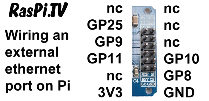
How to wire your ethernet board to GPIO
This is what mine looks like…
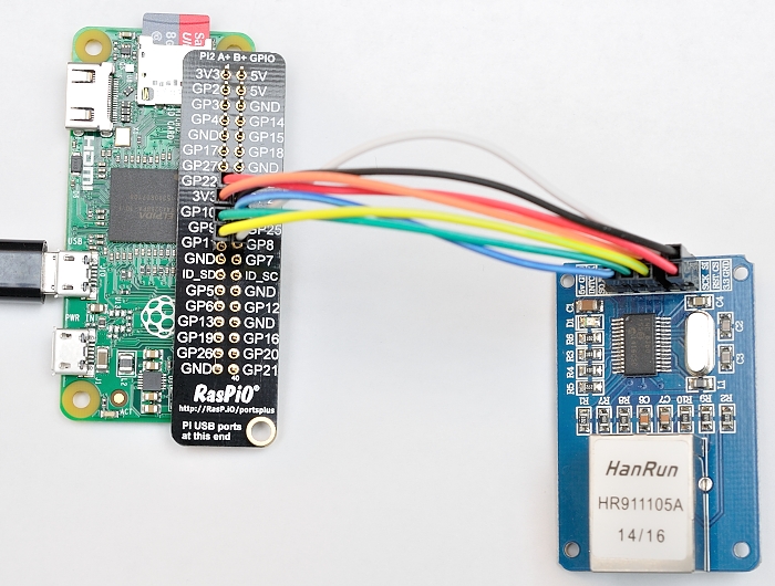
All wired up and ready to go
As usual, I used one of my RasPiO Portsplus boards to make wiring easier on the Pi’s 40 pin header. You can find those here.
I’ve Put a Little Kit together…
If you’d like to have a go at this I’ve put together a little kit which is for sale in the RasPiO online shop.
How Do We Configure It?
Ensure SPI Is Enabled
Menu > Preferences > Raspberry Pi Configuration
Click the Interfaces tab
Ensure SPI is enabled and click OK
If you changed anything, you’ll need to reboot for it to take effect.
Tweak config.txt
Add the following to your /boot/config.txt
dtoverlay=enc28j60
Then when you reboot, your ethernet port should ‘just work’. If you want to tweak the SPI clock speed or INT port you can use dtoverlay=enc28j60,int_pin=25,speed=12000000 and tweak those variables. The ethernet chip is specified at 20 MHz maximum, so best avoid going above that.
Speed Testing
You can use a command line version of speedtest.net if you install it…
sudo apt-get install python-pip

sudo easy_install speedtest-cli
Then run it with speedtest-cli
Speed Test Results
Pi Zero at 12 MHz 3.33 Mbaud down, 2.82 Mbaud up, 39.956 ms latency, 52.19km
Pi Zero at 16 MHz 3.67 Mbaud down, 2.90 Mbaud up, 37.749 ms latency, 43.57km
Pi Zero at 20 MHz 3.88 Mbaud down, 3.10 Mbaud up, 42.474 ms latency, 43.57km
Pi2 with ethernet onboard 74 Mbaud down, 5.86 MBaud up
What does that mean in real money? On my LAN, it took 3m 45s minutes to download an 85 MB file from Pi to Macbook Pro and 3m 18s to upload it to the Pi Zero. So it isn’t going to win any speed awards, and probably isn’t good enough for streaming HD video. But for an Internet of Things (IoT) device or for most purposes it’ll be enough.
It’s Not Supposed To Work
Now I’ve looked at the datasheet for the chip, I’m surprised it works at all.
According to that, page 80 states a power usage of 160 mA which is a lot more than the nominal 60 mA 3V3 rail limit on the Pi. It might therefore be better practice to run it from a separate supply. Your mileage may vary. I hope you had fun. I certainly did.
(Update to add) Sources close to RPi have told me unofficially that it will probably be fine to run this ethernet board on the 3V3 rail of the Pi Zero.
Alex Clever idea perhaps a 3.3v reg from the Zero 5V would be better.
Sent Gordon a email as gpio readall not working on the Zero from the 1/11/15 Wiringpi release. he is looking into it.
Keep up the good work
Terry
Yes a reg from 5V is definitely a possible option. I haven’t actually measured the current draw on the ethernet board, so don’t know if it’s “straining” the Pi or not. But I put the warning there just so people don’t cook their Pis and then blame me for it. :)
Mine seems fairly stable so far.
Looks like some (newer?) versions have a 3V3 reg!
… and the same seller on ebay has 5 (five) suitable voltage converters for a princely sum of £1.10. I haven’t tried this yet but I shall.
It looks like a reg won’t be needed since it works well and I’ve been told unofficially that it should be OK
Texas,
Regarding the current issue connect one of these “DC 4.5-7V to 3.3V AMS1117-3.3V Voltage Regulator Power Supply Module” to the Pi’s DC rail either of the top r/h 5v pins. This drops the 5v down to 3.3v and pulls the current directly from the Pi’s power supply ergo nothing to over cook. They are cheaper than chips I got 10 for £1.35 on eBay.
Pete
powerful
Gordon has just updated “WiringPi” it now covers the PiZero on “gpio readall” command
Nice one. I assume that one could use an USB Port (or the existing connect to a Hub
for expansion) and just add a WiFi Dongle?
Of course, which is exactly what many people do.
Alternatively, if you want to stick to wired Ethernet but don’t want to go the SPI route, you can also get USB-connected Ethernet port dongles.
Your device-tree comments made me giggle Alex :)
In that case they were “fit-for-purpose” and you are not getting a refund on them. :)
I managed the initial setup on my Zero via a Usb Ethernet Dongle that I use with my Tablet. It all worked fine with no additional setup. Once all software was installed I swapped to a wifi dongle. Love the compact size of the Zero, so many options.
May your Speed Problem results in the wiring w/o twisting an shielding the wires?
The way I understand it, Ethernet cables need the twisted-pairs and shielding (to prevent interference on the long cables they use). But the wires between the Pi and ENC28J60 are using SPI, and hence (AFAIK) the twisting and shielding isn’t needed. The ethernet only happens “after” the ENC28J60 chip.
I think the “Speed Problem” is simply that SPI is a much slower bus (comparatively speaking) than USB.
…and a quick google search shows that the ENC28J60 is only a 10Mbps ethernet chip, whereas the LAN9514 used on the Pi2 is a 100Mbps ethernet chip.
Hello.
Did this external Ethernet work fine with RaspberryPi Model B?
On your scheme (How to wire your ethernet board to GPIO) 3.3 goto 3.3 but on your foto (All wired up and ready to go) red wired that connected to 3.3 goto GP22. What that means?
Thanks.
Haven’t tried it on a B.
Parallax error on the photo makes it look wrong, which is why you should always trust diagrams over photos.
Also trust your common-sense. 3.3 should go to 3.3. :)
Thank for your answer.
Based on forum discuss http://www.raspberrypi.org/forums/viewtopic.php?f=44&t=18397
plus your article (I have no IRQ on ENC, so I see where you connect GPIO25, and understand that IRQ is INT) I think that connection will be next
ENC – RPi
=======
VCC – 3v3
GND – GND
CS – CE0 (gpio 8)
SI – MOSI (gpio 10)
SCK – SCKL (gpio 11)
SO – MISO (gpio 9)
IRQ (INT) – GPIO 25
Some think like that
[img]http://i.imgur.com/7eac1F9.jpg?1[/img]
By the way, this ENC28J60 different that yours, not only by date made.
That wiring schema looks OK to me. Are you saying it isn’t working? As Andrew says, you’ll need a recent Raspbian distro for that to work.
No, I didn’t say that.
I even do not connect it, because personally have not even work with GPIO, so I make a consultation with people who already do that.
With ENC28J60 I have 10 pin connector
http://i.imgur.com/B1DPt6W.jpg?1
so there is need an adapter for right connection, or got an individual wires like in case on photo in article.
My current distribution, regular updating by apt-get, is “Linux raspberrypi 4.1.7+ #817 PREEMPT Sat Sep 19 15:25:36 BST 2015 armv6l”,
so from OS only /boot/config.txt may require an update (add dtparam=spi=on and dtoverlay=enc28j60).
alex, AndrewS thanks for your answers.
I used the pinout described here with my ten pin enc28j60 board, and it works great.
I can’t see any reason why it wouldn’t work on a Model B (as long as you’re using an up-to-date OS). With the obvious caveat that it’ll be slower than the built-in Ethernet port.
Hi Alex,
Thanks for posting this. As you say, it “just works”. It only took a few minutes with your excellent instructions :-)
Hello,
Why don’t use a LAN9514 chip on external board (in replacement ENC28J60) connect on mini-usb ? you can reconnect a new ethernet and more usb !
it’s stupid idea ?
C-Y
I used what I had. Perhaps someone else has a board with a LAN9514 on? WJDK.
Not a stupid idea, but LAN9514 boards are a tiny bit more expensive than ENC28J60 boards… ;-)
http://uk.farnell.com/microchip/evb9514/lan9512-enet-phy-eval-board/dp/2321379
Maybe remake just a board with LAN9514:
http://fr.farnell.com/microchip/lan9514-jzx/ic-usb2-enet-cntrl-4-port-hub/dp/2292587
and the block schematic page3 Raspberry-Pi-Rev-2.1-Model-AB-Schematics.pdf
:)
If you have the skills to do so, then go for it!
But I suspect for most people it’ll be easier to add a ready-made ENC28J60 board or a USB ethernet adaptor ;)
(Or just buying a Raspberry Pi B+ or Raspberry Pi 2 is another alternative of course!)
Thank you for another very useful article. I believe this particular ENC28J60 module has a 3.3V regulator on board (underneath, perhaps marked AMS1117-3.3). So, you should be able to power it through the 5V pin instead of the 3.3V pin, and sidestep the 3.3V current limit.
It does. You’re right. I haven’t tried 5V power though as I was unsure if it would then think the logic level was 5V too (not looked into it very far)
I can confirm that using the 5V pin to power via the built-in regulator seems to work fine, with no blue smoke release so far.
I have also tried this with 5V. I have a different board, also with a 3.3V regulator, but from looking at http://www.microchip.com/wwwproducts/en/en022889, it seems the enc28j60 is 3.3V in supply and i/o, so it shouldn’t be a problem? I see no components to convert 3.3V signalling to 5V.
I used these instructions with my Raspberry Pi Model A+. It works great except for one thing:
I assign IP addresses using a MAC ID to DHCP table on my router. The enc28j60 appears to use a different MAC ID every time the Pi reboots. How can I specify a specific MAC ID to use every time?
Thanks
I’ve noticed that happens too. I suppose you could force a static IP address. I know it can be done, but never having done it myself, I can’t tell you how.
I don’t have an ENC28J60 myself, but I did a bit of digging…
The enc28j60 MAC address is randomised at bootup, because just like the LAN9514 chip used on Pis with built-in Ethernet, the MAC address needs to be programmed from an external EEPROM (see http://www.microchip.com/forums/m435924.aspx ). The boards being used here obviously don’t have an EEPROM, so you need to program the MAC address yourself (at runtime). On the Pis with a LAN9512/LAN9514 chip (B, B+, Pi2) the MAC address is automatically calculated from the Pi’s serial number, and the firmware adds a kernel command-line parameter (smsc95xx.macaddr=B8:27:EB:xx:yy:zz), which is read by a RPi-kernel-specific module parameter (see https://github.com/raspberrypi/linux/commit/683a06a250e735c94ec3640d9288528ee50ddf16 ).
The ENC28J60 DeviceTree overlay (see https://github.com/raspberrypi/linux/blob/rpi-4.1.y/arch/arm/boot/dts/overlays/README#L204 and https://github.com/raspberrypi/linux/blob/rpi-4.1.y/arch/arm/boot/dts/overlays/enc28j60-overlay.dts ) doesn’t seem to offer any way of setting the MAC address, but the actual kernel driver itself does (see http://lxr.free-electrons.com/source/drivers/net/ethernet/microchip/enc28j60.c#L1537 ), so possibly something like http://www.aboutlinux.info/2005/09/how-to-change-mac-address-of-your.html would do the trick? (which I guess you’d want to run from a startup script to ensure the same MAC at every bootup – see e.g. http://www.raspberrypi-spy.co.uk/2015/10/how-to-autorun-a-python-script-on-boot-using-systemd/ but ignore the Python bits)
Alternatively I guess you could try hacking something like https://github.com/raspberrypi/linux/commit/683a06a250e735c94ec3640d9288528ee50ddf16 into https://github.com/raspberrypi/linux/blob/rpi-4.1.y/drivers/net/ethernet/microchip/enc28j60.c , compiling your own kernel module, and then adding a enc28j60.macaddr=aa:bb:cc:dd:ee:ff parameter to your /boot/cmdline.txt .
Thanks for your help. I made a startup script with those commands, and the problem is solved!
Yay! :-D
hahahahahah NERD!
Thanks, I prefer the term “geek” myself :)
Here is a somewhat simpler way to assign a fixed MAC address at boot time:
1) Create the file /lib/systemd/system/setmac.service
Add the following contents:
[Unit]Description=DSet the MAC address for the ENC28J60 enet adapter at eth0
Wants=network-pre.target
Before=network-pre.target
BindsTo=sys-subsystem-net-devices-eth0.device
After=sys-subsystem-net-devices-eth0.device
[Service]
Type=oneshot
ExecStart=/sbin/ip link set dev eth0 address 00:00:00:00:00:00
ExecStart=/sbin/ip link set dev eth0 up
[Install]
WantedBy=multi-user.target
Change the MAC address to whatever you want. Be careful, the first byte must be 00
make the file mode 644
Execute the following two commands to enable the service
sudo systemctl daemon-reload
sudo systemctl enable myscript.service
Reboot.
Hi,
I’ve tried running the script to set the MAC, no joy….
No matter how I try to run it, it always fails..
“sudo systemctl enable setmac.service” gives Job for setmac.service failed…
“sudo systemctl enable myscript.service” gives Failed to execute operation: Invalid Argument
I’d really like to have the lanport grab the same IP, but whatever I do, it keeps bed hopping!!
TIA,
Paul.
I dont know about the ethernet address but I set a static IP address for my zeroPi running Jessie as follows. Of course add your own ip addresses but note the /24 after the static ip address (but I don’t know why – just cribbed from others on various forums)
For static IP on an ethernet connection:
sudo nano /etc/dhcpcd.conf
Then type in the following lines into the file:
#for wired:
interface eth0
static ip_address=10.0.1.181/24
static routers=10.0.1.1
static domain_name_servers=10.0.1.1
#for wireless:
interface wlan0
static ip_address=10.0.1.171/24
static routers=10.0.1.1
static domain_name_servers=10.0.1.1
then do a sudo reboot to take effect.
This may not be what you are after, but I hope it helps and it works for me.
Ta for the info…
It’s the MAC I need to be static, as I use DHCP with strict bind MAC reservations for my outside facing kit..
I’ve set a static IP as shown, and it appears to work.. Only time will tell if the Pi Zero and the cheapo adapter will work as I need them to, or do I just bung in a B+?
Thanks for the info!! :-D
https://github.com/raspberrypilearning/networking-lessons/blob/master/lesson-1/rpi-static-ip-address.md shows the more usual way to set a static IP address.
And since you seemed curious, the /24 on the end of the IP address is an alternative way of specifying the 255.255.255.0 netmask, as it signifies the first 24 bits (out of 32) in the netmask are 1. https://en.wikipedia.org/wiki/Classless_Inter-Domain_Routing
But be careful, because different config files may expect the info provided in different formats.
Hi Andrew, thanks for the info. Editing the /etc/network/interfaces file for a static ip as per your link was what I did when using wheezy but my new zero pi came with Jessie and the interfaces file says:
# Please note that this file is written to be used with dhcpcd
# For static IP, consult /etc/dhcpcd.conf and ‘man dhcpcd.conf’
so hence I edited the dhcpcd.conf file. Actually I can remember exactly what was in the wheezy pi interfaces file as I’ve moved all on the Jessie. But mybe I’m doing it all wrong??
Oooh, I didn’t know that, I always just rely on dynamic addressing! I’ll have to do a bit of experimentation at some stage, and perhaps the Raspberry Pi Learning Resource needs updating?
Paul wrote:
>“sudo systemctl enable setmac.service” gives Job for setmac.service failed…
>“sudo systemctl enable myscript.service” gives Failed to execute operation: Invalid Argument
Yes. It looks like I had a typo. The command should be “sudo systemctl enable setmac.service” However, the error you noted for that command you entered would seem to indicate there is a typo in the setmac.service description. Check /var/log/messages to see if there is any more detailed information.
How about Real time clock , How can I add ?
Please tell me.
It’s not something I’ve yet tried, but I think Matt Hawkins blogged it over at raspberry pi spy
The 40-pin GPIO header on the Pi Zero is the same as the GPIO header on the Pi B+, so any of the usual Raspberry Pi RTC addons will be fully compatible…
https://www.google.co.uk/#q=raspberry+pi+rtc
Thanks for the info, I now have an ethernet running on my zeroPi. What I’m not sure about, being a noob, is if the pins used for the ethernet can also be used for other purposes at the same time. In particular can I use the Dunino board at the same time? Sorry for a dum question.
Unfortunately the Duino uses the SPI pins for its programming, so no I don’t think you can use them both at once unless there is a way to tweak the chip select on the ethernet driver to use GPIO7(CE1), as it’s hard-wired on the Duino.
I suspect there’s probably a way to configure which SPI chip-select gets used for which driver by doing something with the DeviceTree stuff ( https://www.raspberrypi.org/documentation/configuration/device-tree.md ), but not being familiar with DeviceTree myself (nor having an ENC28J60), I wouldn’t know where to begin. Best bet is probably asking on the Raspberry Pi forums http://www.raspberrypi.org/forums/
If you do find a solution, keep us updated :-)
Just maybe something here – http://discohat.com/miscap/ – not sure thought. (I’ve got one of these boards from a knowledgeable Mr Karri, but found my ENC28J60 board was different to the one required for this board – though I did have the same as the one as in this rpi-tv article).
This board comes with dip switches and appears to allow for 2 alternative pin selection for the ethernet board. One with pins 8,9,10,11,25 and one using pins 18,19,20,21,17. However I may have misunderstood this entirely as this is my first foray into electronics. Theres a nice electronic schematic on the site which you may understand.
However, whatever pins are used I expect they may interfere with the Duino board. I was thinking a combination of the ZeroPi and Duino would be an excellent choice to create some smallish sensor nodes. A Pi in each node may be a bit OTT, but at £4 a pop, why not. I would need network comms, preferably wired hence my interest in getting wired ethernet to work, but wireless may suffice I will experiment some more.
Thanks to all.
A few different bits of terminology, which can be confusing to a beginner, so I’ll try to take things slowly (without sounding patronising!)
When you use an SPI bus (with the Raspberry Pi being the ‘master’ device), it’s possible to hook up multiple ‘slave’ devices to the same MOSI, MISO and CLK pins, as long as each slave device uses a different CS (ChipSelect) pin. The Raspberry Pi then uses the CS lines to tell all the connected slave devices which one is “currently active” (any inactive slave devices ignore the signals on the SPI bus). https://en.wikipedia.org/wiki/Serial_Peripheral_Interface_Bus#Independent_slave_configuration
On the Raspberry Pi, the “SPI0” bus (which is available on both the 26-pin-header Model A/B Pis and 40-pin-header Model A+/B+/2B/Zero Pis) has two CS pins labelled CE0 and CE1. In earlier comments, myself and Alex were referring to connecting both the Duino and ENC28J60 to this SPI0 bus, with the Duino using CE0 and the ENC28J60 using CE1. (although having just looked at the Duino manual, I’m not sure if it actually uses either of the CE lines?)
However on the 40-pin-header Model A+/B+/2/Zero Pis there’s *also* an additional (separate) “SPI1” bus available, which has 3 ChipSelect pins (see http://elinux.org/RPi_BCM2835_GPIOs for full details). The approach taken by the ‘miscap’ board seems to be manually switching the ENC28J60 between SPI0 and SPI1 (using the CE0 of each), rather than switching the CS/CE of the SPI0 bus; and you did indeed read the schematic correctly (although strictly-speaking it’s more correct to call them *GPIOs* 8,9,10,11,25 and *GPIOs* 18,19,20,21,17, rather than the (physical) ‘pins’ that you referred to). It seems a bit short-sighted for the miscap board to assume a particular ENC28J60 header pinout :-/ The https://rasp.io/duino/ is designed to work with the first 26-pins of the GPIO header only (so that it works with all flavours of Pi), and so the pins needed for SPI1 are still free :-)
**However** (and I may well be wrong here, as I haven’t been following things very closely) AFAIK there’s not yet a native Linux driver available for the SPI1 bus on the Raspberry Pi? Google doesn’t turn up much either https://www.google.co.uk/search?q=Raspberry+Pi+SPI1 only hinting that there’s a 3rd-party library that supports it (which I guess wouldn’t work with the ENC28J60 driver?). Although to fill in the gaps in my knowledge, I’d be very interested to hear if Karri did get the miscap working with SPI1.
(And just for SPI-completion, there’s also a “SPI2” bus with 3 ChipSelects which is only accessible on the Compute Module, which again doesn’t have a driver yet AFAIK.)
Alternatively, you could look at using a wired USB Ethernet interface, as I mentioned in earlier comments.
Or, if you’re not going to be re-programming the Duino at the same time as using Ethernet (which I assume will be the case for sensor nodes), you could program the Duino with the Ethernet disconnected, then move the programming pins on the Duino, and then connect the ENC28J60 to the (now unused) SPI0 pins as usual.
And the final option would be to bypass the Pi, and just connect the ENC28J60 directly to the Duino running in ‘standalone’ mode.
Lots of different possibilities, which is part of what makes hacking so fun! :-)
From memory Andrew, CE0 is hard wired to the reset pin on the atmega and also pulled up via a 10k resistor. Although the protocol is bit banged, the correct pins were used that it could be native spi as well.
Thanks to AndrewS for the detailed info which is very helpful for a beginner, much appreciated. Lots of different possibilities indeed. :-)
Just out of curiosity Alex, is the schematic for RaspioDuino available anywhere?
If the CE0 of SPI0 is connected to the reset pin on the atmega, then I suspect you couldn’t use two devices on the SPI0 bus, because whenever the Pi switched which slave-device it was talking to, then the atmega would get reset? Which may or may not be a problem, depending on what your duino sketch actually does ;-)
I’m afraid there is no schematic because I laid out the board in PCB mode directly. The pullup would prevent that though wouldn’t it? (I’m not sure about that – or the exact protocol details of SPI).
A project has been lauched on Kickstarter that uses this Ethernet chip to add ethernet to Raspberry PI zero: https://www.kickstarter.com/projects/755102253/pijack-add-ethernet-to-raspberry-pi-zero
Nice, but it’s a shame it doesn’t include the HAT-style eeprom for that price. If I plugged it onto a B+, and did the config.txt edit, would I then automatically get eth0 and eth1?
Hmmm, given that the RaspberryPi has two ChipSelect lines on it’s default SPI interface, that’s now got me wondering if it’d be possible to hook up two of the ENC28J60 breakout modules Alex uses in the original article, to get eth0, eth1 *and* eth2 on a B+ or Pi2…? ;-)
There’s only one way to find out. I’ve only got one myself.
any idea to plug TWO ethernet, at the same time?
Thanks brother very helpful, works greet
Is there a list of network chips this procedure should work for?
For example, I understand linux implements a full tcp/ip stack, but the driver for the actual ethernet hardware must be developed and somehow configured to hook into what linux expects?
I’m using a Lantronix ethernet solution, that communicates via a uart (ttl rs232), what would be the general steps involved in getting this to work with linux?
Can you provide the exact model number of the device you’re trying to use? I had a poke around on the Lantronix website, and it seems like they sell “serial communication encapsulated over an ethernet connection” modules, rather than “ethernet networking via a serial connection” modules. I.e. the uart device that the lantronix module is talking to thinks it’s directly connected to another computer via a null-modem cable, so in fact there’s no special driver-software that needs to be written. But it’s only a point-to-point null-modem-like connection, and can’t be used to add full networking capabilities. (unless you wanted to start mucking about with PPP)
I guess it’d be a bit like SSHing from your PC into a Pi B+, and then using minicom to talk to a PiZero connected to the B+’s UART. The PiZero only ‘sees’ the UART connection, it doesn’t suddenly become network-enabled, even though it’s indirectly communicating with your PC over an ethernet connection.
Plenty of old RTL8139 PCI NIC cards kicking about. Should be possible to pick off the power and IO s from the edge connector, all of which are utterly standard? With a Zero costing a mere £4, it’s not smart to shell out another £3 for another commercial dongle to add an ethernet port? Just need to know the interconnects. Anyone able to help please?
That’s far more effort than it’s worth. And even if you *did* have a software driver to bit-bang a PCI bus over GPIO pins (I dunno if such a thing is even possible), the PCI bus is 32-bit (along with interrupt pins etc.), whereas there are only 28 GPIO pins available on the RPi’s 40-pin header.
http://pinouts.ru/Slots/PCI_pinout.shtml
http://pinout.xyz/
Hi,
First off, thanks, great article, just what i needed :)
Do you know if you can add 2 of these to a PiZero at once? could you use the 2 chip enable pins, one connected to each module? If so does anyone know how to get the Pi to recognise each module? Would love to be able to place a PiZero with 2 ethernet ports connected to it, into a VERY small case.
thanks again for a great article
Matt
It might be possible to do that by messing about with some of the DeviceTree stuff, but I dunno how to do that myself. My earlier comment might have some useful links https://raspi.tv/2015/ethernet-on-pi-zero-how-to-put-an-ethernet-port-on-your-pi#comment-60275
Thank you sooo much for this, works like a charm.
Perfect for integrating a Pi Zero as printserver directly into my printer.
Tobias,
Please give a few more details. Surely there’s much sw work to do? As in “drivers”? Will a printer driver that happily prints to a USB printer, just as easily find it and send jobs to it once it’s “networked” via Alex’s creative hack?
I have visions of taking my very capable USB flatbed scanner and doing the same. But I balk, thinking of drivers that expect a USB scanner.
I’d like to hear all about your success.
Dave
This discusses the details of sharing a printer and scanner connected via Alex’s creative hack:
http://www.raspberry-pi-geek.com/Archive/2013/01/Converting-the-Raspberry-Pi-to-a-wireless-print-server/(offset)/4
More reading to do…
Dave
Yeah, that’s looking at using “standard” printing and scanning network protocols (CUPS, etc.), and is probably your easiest option https://en.wikipedia.org/wiki/CUPS
But if you want “pure” USB over network (which in theory might allow you to use features not directly supported by CUPS) you could have a look at http://usbip.sourceforge.net/ although it’s something I’ve never looked into myself. Or https://www.raspberrypi.org/forums/viewtopic.php?f=36&t=36851
Hello, I just bought one of these, it has the same part number, but two less pins. The download speed is okay, but when I upload, I get a kernel panick. The pins are labelled slightly differently as well.
Mine has CLC, WOL, SI, CS 3v3, NT, SO, SCT, RST and GND. I used SI for ST, SCK for SCR, NT for LNT.
Any tips would be welcome :)
Sounds like that might be a question for https://github.com/raspberrypi/linux/issues
If the downloading works then the SPI protocol between the Pi and the ethernet chip is obviously working okay, so perhaps you’re getting a kernel panic because your board has a slightly different revision of the ethernet chip?
Oooh, just spotted this: https://github.com/raspberrypi/linux/issues/1385
Looks like the kernel panic might be fixed if you do an rpi-update to get the latest bleeding-edge kernel :-)
Oh yes :) I had to use a USB Nic to do the update (I did sudo apt-get upgrade, sudo apt-get update, then sudo rpi-update) and the little board works like a charm. I get 4Mb/s down and 3Mb/s up (on a normal PC I would get 50Mb/s down and 18Mb/s up)
The reason I wanted to use this was mainly because cheap USB/NICs seem to drop out a lot, and expensive ones work but anything that costs 3x the pi zero is a bit pointless. Now I also have a free USB port.
Nice work chaps.
Found another use for this, reflashing hosed BIOS chips on laptops after a mishap involving a “required update” that didn’t check battery state before flashing (standby=dead BIOS). In fact this could probably be done in-circuit and include a facility to read back the old (dead) chip’s binary image to see what broke.
Interestingly on some laptops it still responds to pings on the NIC in 10 base T mode so perhaps the problem is recoverable with some “The Martian” level binary hacking?
I know that many will use this very creative bit of kit to add networking to their pi. But I like the possibility of USB over IP. As a means to network a USB peripheral, it doesn’t seem that simple.
Being a complete Rpi Noob (but some experience with Arduino), my question is naturally one of a noob:
Does this give me a networked USB peripheral? After fashioning the Zero + Ethernet, can I plug my USB printer or scanner into this and network the peripheral? Will USB drivers recognize the peripheral and treat it as if it were USB-connected?
After typing that, I’ve convinced myself that the answer is “No”. But…?
Thanks.
Very interesting. I have a project starting up where I just want to see how many I can run from a single ATX psu. Given that there are a good number of Amps available at 3v3, 5v, and 12v, and the fact that I don’t have an oscope to measure for myself, what could I expect a zero to draw in total using OTG to power and communicate with the head node of a cluster? I understand there is a 128 USB node (including the hubs) limit due to USB specs. I am planning to power the hubs and zeros separately, and just use them for the comms portion.
I don’t need arguments about how serious power can’t be gotten using a zero-node cluster, I just need to find out what a zero will generally draw at 3v3 and 5v on an OTG connection.
Anybody know?
All models of Pi are only powered by 5V, there’s no 3V3 input. The power consumption is probably very similar to https://raspi.tv/2015/raspberry-pi-zero-power-measurements
I’m curious, have you noticed how consistent the speed results are with this? With my wifi adapter, it may be quite a bit faster than these results you have here, but it can drop pretty significantly from time to time. Of course there could be any number of factors that contribute to this (such as other devices on the network).
Has anyone found any good low-profile NICs for the Zero? I currently have some of the USB dongle things, but for some reason they’re all designed in this horrible way that makes them so unwieldy and easily doubles or triples the footprint of the Pi Zero. I have two Pi Zero’s hooked up to my CCTV DVR and I would love for them to just be mounted on the back of the DVR, but these stupid USB NICs add so much overhead (size-wise).
I just got a couple of these HanRun’s in the mail today. I’m going to try one and see if the speed will work for me. If it does, then this will be a perfect solution. Thanks!
I just loaded this up and it seems to work ok. I took 3 different Pi Zeros, one with Wifi (USB), one with a LAN Cable (USB), and then this one with a LAN cable (SPI) – did 3 different speedtests with each, these are my results:
SPI Adapter (wired):
Test #1 – 3.85 mbit/s — ping: 27.221
Test #2 – 3.95 mbit/s — ping: 25.249
Test #3 – 3.85 mbit/s — ping: 24.533
Average – 3.883 mbit/s — ping: 25.667
USB Adapter (wired):
Test #1 – 61.87 mbit/s — ping: 21.955
Test #2 – 63.61 mbit/s — ping: 25.889
Test #3 – 62.22 mbit/s — ping: 21.193
Average – 62.566 mbit/s — ping: 23.012
USB Adapter (wireless):
Test #1 – 2.19 mbit/s — ping: 29.123
Test #2 – 2.22 mbit/s — ping: 35.516
Test #3 – 2.45 mbit/s — ping: 28.468
Average – 2.286 mbit/s — ping: 31.035
As you can see the USB wired NIC is significantly better, however, surprisingly the wired SPI adapter is marginally better than the wireless USB NIC (and quite close to the USB wired one, in terms of ping). Note, my wireless Zero is sitting about 1.5 rooms away from the AP.
One odd thing, my switch doesn’t get a link light – or, it kinda does, just SUPER dim! See attached pic (port #18 – I’ve tried several, all have the same results). The link light on the SPI adapter itself works fine. http://i.imgur.com/k1fCeRd.jpg
I got yesterday my ENC28J60 module, looks exact as yours on the web. I have tried to follow instructions to perfection , still no success in getting ann ip adress.. What puzzles me most is the interconnection between the PiZero GPIO’s and the ENC28 headers
I finally made it working. Main problem actually was interpretation of understanding the labelling on the ENC-module.
This is my interconnection pinout
RPiZero GPIO #——————–ENC28J60 PinLabel
17—————————————– Q3 3,3v
19——————————————ST
21——————————————SO
22——————————————INT
23——————————————SCK
24——————————————CS
25——————————————GND
Just did this to my own pi zero, as part of a project supplementing my final year uni project, worked a treat – Thank you for the steps – Legend!
Thanks Alex, worked first time on Pi Zero
Thanks.
This literally just saved me a lot of headache with Rpi Zero and Minibian which has no wifi firmware installed by default so no networking without a USB LAN card (which I didn’t have handy).
I have exactly the kind of “box of things I’ll use someday” and it had one of these sitting there waiting for some Arduino project (which never came because I got a few ESP8266’s to handle the networking wirelessly).
This is a mega-noob question… to add two of these to the SPI bus… wire up MOSI,MISO,SCLK to both, then seperate CS pins… then use two seperate dtoverlay= lines in config.txt with different INT pins??
That’s not a noob question at all! In theory that should work, but it depends if the kernel driver-code supports it…
And obviously with two devices sharing the same SPI bus you’d halve the maximum bandwidth of each chip.
Thank you for putting the guide together.
Where is the networking enabled? eth0?
I have the ten pin version of this device, and while I’m sure I’ve connected all the pins correctly to the Pi Zero’s GPIO, I cannot get networking to work when the Pi starts.
My device is slightly different than the one shown here.
Mine says “HanRun HR911105A 14/32” and the markings in the chip itself read “ENC28J60-I/SO 1511BG4”.
All the pins I am supposed to use for connecting to the GPIO are are there, though, with the same labelling, so I was expecting it to work.
Any ideas on how to troubleshoot?
I’m happy to report that this is resolved: there was nothing wrong with the wiring or the config.txt setup, etc.
Rather, I hadn’t soldered one of the pins on to the Pi Zero’s GPIO connector properly, and that was the problem.
WARNING !! Please be aware that these boards do not pass Fcc/IEC standards. They all fail in the 200 Mhz range (when in use).
source of information?
If you want to go cheap and use a 17/02 version of the model – chiefly because it uses the same chip, looks similar and costs less, these are the connections that worked here
…………….PI ZERO………………………………17/02…………………………….
….3.3V = .17 | -…………………………..NC —– .CLK | NT. —– GP25
GPIO10 = .19 | – ………………………….NC —- .WOL | SO. —– GP09
GPIO09 = .21 | 22. = GPIO25………..GP10 —– .SI | SCK. — GP11
GPIO11 = .23 | 24. = GPIO08………..GP08 —- .CS | RST. ——- NC
…..GND = .25 | – ………………………….3.3 —– .VCC | GND. —- GND
I’m very happy with the results, thank you for the Tutorial and Configuration write-up (and thanks to my friend Steve for figuring these particular pin-outs for me.)
I have written an adaptation of this post for use with a little bit different Mini ENC28J60 https://blog.stigok.com/post/adding-an-ethernet-port-to-a-raspberry-pi-zero
I would try to complement the speedtests with a simple lighttp server serving a random file 100M file in RAM. Speedtest is in python and might cause some CPU usage to craft the packets. I hit this problem years ago with an iperf server running on openwrt routers.
Really helpful article, particularly pin out explanation – thanks!
is it possible to connect to the Raspberry pi zero more then 1 Ethernet connector ? using this method ?
Thanks for this test, now I have an idea of the speed with this configuration. Now I have to found it in my ” one day it can serve” boxes.
In order to not overload the 3.3v rail of the RPI, you can use the 5v power pin, there is a 3.3v voltage regulator behind it (on the other side of the board)
I think you can
bravo, thanks !
bravo thanks !
Very nice, can you give us the dimensionof the ethernet board (with hole diameter and spacing) ?
Approx. 50mm by 33mm. Just buy a few to test with – they’re less than £2 each on eBay.
I’ve had a lot of network instabilities running from the 3.3V rail, so I switched to 5V and now it’s a lot more stable.
The ENC28J60 now runs at my home for 2 years, connected with one of the first Pi Zero’s made. It runs a Domoticz server. Wired up as in the original scheme. No voltage or current issues ever ! So highly recommend this original setup !
Awesome :)
After over 3 years of flawless service now my enc28j60 does not connect …
what to do. how can i troubleshoot ?
Please check in config.txt is dtoverlay=enc28j60 still there.
Appears to be a software problem… !
I have three of these for my zeros I was worried about the current issue especially as zeros are thin on the ground at the moment some are for sale for over £30. I found these little cct boards on ebay that drop anything from 12v down to 3.3v and was thinking of putting one between the 5V vcc and the module OR just use the 5V direct as the pin is labelled 5v. What would you suggest.