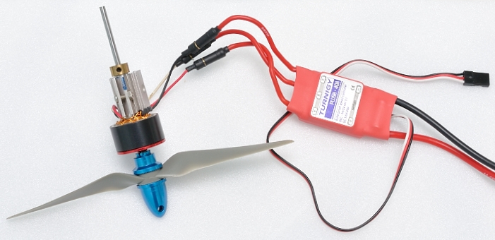
I’ve recently become interested in making “machines” of various sorts. I was sorting through some of my RC (radio control) plane “stash” the other day and came across various brushless motors and electronic speed controllers (ESC) like these. In RC, Brushless ESCs are usually connected to a radio receiver which generates servo control pulses.
So this morning I thought it would be fun to try and get a Wemos D1 mini controlling a brushless motor. I’ve done similar before. I can remember, back in the dark ages of 2013, using a Guzunty Pi to generate servo control signals to drive a brushless ESC.
I’ve also controlled servos directly with Arduino before now. This is handy because Wemos D1 mini can use the Arduino IDE. There’s also a ‘servo’ library that we ought to be able to use.
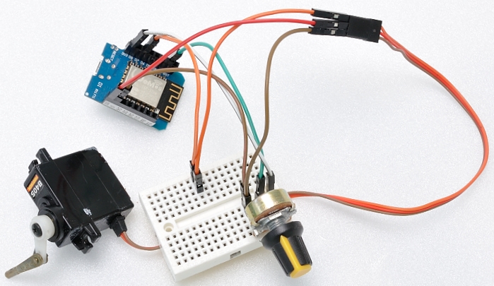
So, for a quick and dirty test, I wired up a servo, a Wemos D1 mini and a potentiometer
…and ran the sweep sketch…
/* Sweep http://arduino.cc/en/Tutorial/Sweep */
#include <Servo.h>
Servo myservo;  // create servo object to control a servo
                // twelve servo objects can be created on most boards
void setup()
{
  myservo.attach(2);  // attaches the servo on GIO2 to the servo object
}
void loop()
{
  int pos;
  for(pos = 0; pos <= 180; pos += 1) // goes from 0 degrees to 180 degrees
  {                                  // in steps of 1 degree
    myservo.write(pos);              // tell servo to go to position in variable 'pos'
    delay(15);                       // waits 15ms for the servo to reach the position
  }
  for(pos = 180; pos>=0; pos-=1)     // goes from 180 degrees to 0 degrees
  {
    myservo.write(pos);              // tell servo to go to position in variable 'pos'
    delay(15);                       // waits 15ms for the servo to reach the position
  }
}
…which is a built-in demo sketch that makes a servo cycle from 0 to 180° and back again – forever! It worked perfectly. YAY! We’re getting there.
Now We Need Pot Control
Next step was to incorporate the analog port to read the potentiometer and set the servo position accordingly.
/* Modified combination of sweep and knob, http://arduino.cc/en/Tutorial/Sweep
*/
#include <Servo.h>

Servo esc;  // create servo object to control a servo
int val;        // variable to read value from analog pin

void setup()
{
  esc.attach(D7);  // attaches servo on D7 to the servo object
}

void loop()
{
  val = analogRead(0);               // reads potentiometer value (between 0 and 1023)
  val = map(val, 0, 1023, 0, 180);   // scale it to use it with the servo (between 0 and 180)
  esc.write(val);                    // sets servo position according to scaled value
  delay(15);                         // waits for servo to get there
}
This also worked perfectly with a servo. Twiddle the potentiometer and the servo moves accordingly. YAY!
And Then it Got Harder
“This is easy – I’m on a roll” so I hooked it up to the brushless ESC instead of the servo and…
Nothing happened! GAH!
So I took out my trusty “servo driver” and tried the ESC with that.
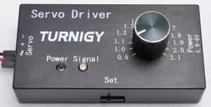
Turnigy servo driver gives out correct pulses to control a servo (it has an ATMEGA inside – I looked)
It worked fine. “Oh!” I thought. The wiring looked good, so maybe it’s something to do with the Wemos‘ 3V3 logic levels? So I tried a level shifter to output a 5V signal. This didn’t help (you’ll see why later on).
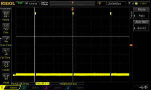
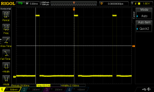
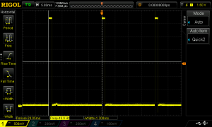
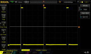
So, fresh out of excuses, I decided to “get the ‘scope’ on it” and see exactly what was happening with the signals.
Oscilloscope Results Proved Revealing…
| Servo Driver | Wemos D1 mini | |
|---|---|---|
| Frequency | 50 Hz | 49.9 Hz |
| Period | 20.00 ms | 20.05 ms |
| Pulse width low | 0.935 ms | 0.6 ms |
| Pulse width high | 2.115 ms | 2.4 ms |
| Logic level | 3.22V | 3.34V |
The only appreciable difference was in the pulse widths. But since pulse width is the language of servos, it matters. The Wemos “zero point” of 0.6 ms is a lot lower than the 0.9 ms of the servo tester.
So you can see our Wemos is pushing out a pulse width that is rather too low. The way servo pulses are supposed to work, a servo would be at 0° at 1.0 ms, 90° at 1.5 ms and 180° at 2.0 ms pulse width. The ESC was not recognising the 0.6 ms pulses and thus refused to activate.
Let’s Test the Range
While I had the oscilloscope on the servo tester, I measured the ‘actual’ pulse width settings that affect the motor’s behaviour. I found that, below 1.25 ms the motor wouldn’t spin up and it reached maximum speed at 1.78 ms. This data would prove useful later on.
The data also showed why the logic level shifter didn’t change anything, since the ESC is triggered on 3V3 logic anyway. (I was firing blind before I scoped it).
With some further experimentation, changing the degree values in the sketch enabled me to tweak the output so that not only did the ESC react to the Wemos output, but it was fine-tuned to make best use of the ‘reactive range’. The ESC only changes the motor speed between 1.25 and 1.78 ms so I tweaked the sketch iteratively until I hit upon figures of 65° for LOW and 130° for HIGH. This meant that the full range sweep of the potentiometer was in use instead of having large ‘dead’ zones at each end where nothing changed.
Final Tweaked Sketch
/* Modified combination of sweep and knob, http://arduino.cc/en/Tutorial/Sweep
   tweaked for a Turnigy Plush 40 brushless ESC
*/
#include <Servo.h>

Servo esc;  // create servo object to control a servo
int val;        // variable to read value from analog pin

void setup()
{
  esc.attach(D7);  // attaches servo on D7 to the servo object
}

void loop()
{
  val = analogRead(0);               // reads potentiometer value (between 0 and 1023)
  val = map(val, 0, 1023, 65, 130);  // scale it to use it with the servo (between 65 and 130)
  esc.write(val);                    // sets servo position according to scaled value
  delay(15);                         // waits for servo to get there
}

/*  65 degrees corresponds to 1.21 ms pulse width. Turnigy plush 40 won't spin motor until 1.25 is reached
 * 130 degrees corresponds to 1.87 ms pulse width. Turnigy plush 40 maxes motor out at 1.78 ms
 * If you use 0-180 the ESC won't spark up the motor at all, pulse needs to be >= 0.9 to get a response
 * But also if you use 65-130 degrees you maximise the usable range of the potentiometer, so there's
 * hardly any dead space. Gives you much better control along the range of movement
 */
Hope You Enjoyed the Story
Now I’ve got it all working exactly as I wanted it to. It took a bit longer than I thought it would, but it was educational.
I had fun with this and got to use my oscilloscope again. It would have been very difficult to debug this issue without one. Several of the parts I used here are available in the RasPiO online store. Come and have a look…
Interesting – one question. The oscilloscope features you used during this venture amount to just about all I can ever imagine needing an o-scope for in my projects. I’ll never work with analog circuitry and I’m unlikely to ever need to think about complex waveforms, but I can imagine needing to spy on PWM type signals.
So my question is, would this ultra-cheapie scope do the job? https://www.ebay.com.au/itm/262673279429
It seems to include several of what I assume are the right capabilities:
Maximum real-time sampling rate : 1Msps
Accuracy : 12Bit
Sampling buffer depth : 1024 bytes
Analog bandwidth : 0 – 200KHz
Vertical Sensitivity : 10mV / Div – 5V / Div ( 1-2-5 progressive manner )
Adjustable vertical displacement , and with instructions
Input impedance : 1MΩ
Maximum input voltage : 50Vpp (1: 1 probe ), 400Vpp (10: 1 probe )
Coupling modes include DC / AC / GND
The horizontal time base range : 10μs / Div – 50s / Div ( 1-2-5 progressive manner )
With automatic, regular and one-shot mode , easy to capture the moment waveform
Available rising or falling edge trigger
Adjustable trigger level position , and with instructions
Observable trigger waveform before ( negative delay )
Can freeze at any time waveform display (HOLD function )
Comes 1Hz /3.3V square wave test signal source
Thanks for the post BTW – I came here for the RPi.GPIO basics series but saw this one in the sidebar…
at that price you’ve got nothing to lose. I’d give it a go and see :)
i know this a bit old ,that ebay link is only for the case ,,,this like is case and scope .
https://www.ebay.com.au/p/Dso138-2-4-TFT-Digital-Oscilloscope-Acrylic-Case-DIY-Kit-SMD-Soldered/18008510737?iid=322977728021
Heh – I bought both about a month ago, just ‘cos I couldn’t resist the gadget… I assembled it, made sure it powered up, and it’s been sitting on the corner of my bench ever since. I’m not sure when I’ll get around to even learning how to use it! But, now I own an oscilloscope.