The power circuit on the new Raspberry Pi B+ has been completely redesigned. It now has an efficient switching regulator. So I decided to take my trusty emeter, a tool I spent far too much money on a few years ago whilst in the grip of the aero-modelling ‘bug’, and make some measurements.
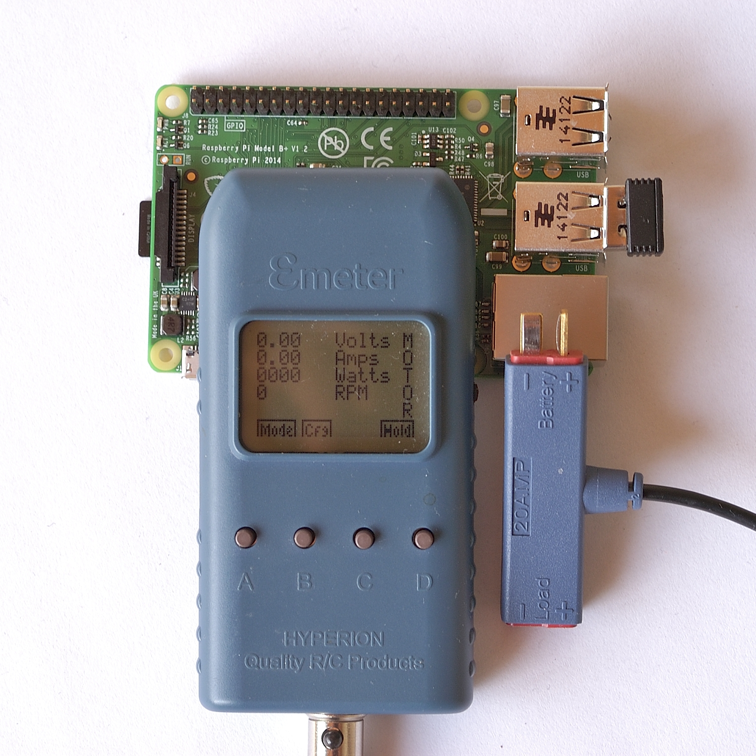
Emeter with Raspberry Pi B+
I measured the current and voltage going into the Raspberry Pi. The emeter has a calibrated shunt (small blue rectange in the photo with ‘battery’ and ‘load’ at each end) that’s good for up to 20 Amps. This is a way of measuring without disturbing the circuit. (It measures the voltage drop across a fairly low-value resistor.)
I did these measurements on both a late rev 2 model B and the new B+. Both were measured with just a wireless keyboard dongle AND with both keyboard dongle and Edimax wifi dongle (which uses an additional 40-50 mA).
The results are in the video, which also shows hot-swapping a wifi dongle without the Pi rebooting…
Here are the numerical results as well as a couple of extras (Watts = Volts x Amps)…
Just Keyboard Dongle
B: 4.98 V, 0.38 A, 1.89 Watts
B+: 5.03 V, 0.24 A, 1.21 Watts
Keyboard Dongle + Edimax Wifi Dongle
B: 4.98 V, 0.43 A, 2.14 Watts
B+: 5.02 V, 0.28 A, 1.41 Watts
Some B+ Only Measurements
With Camera Module Attached
Idling: 5.12 V, 0.21 A = 1.07 Watts (done at different time from above, so slight drift accounts for difference in baseline value)
Shooting video: 5.07 V, 0.27-0.33 A = 1.37 – 1.67 Watts
This was interesting because the camera clearly and repeatably used more power when pointed at a bright light than something darker. I could make it go from 0.27 A to 0.33 A at will. So if you’re using the camera in very bright conditions, you might find it uses a bit more power.
With the USB/LAN Chip Disabled:
5.09 V and 0.15 A = 0.76 W
In a Shutdown State
5.23 V, 0.05 Amps = 0.26 Watts
Overall
So we can see that the new Raspberry Pi B+ uses 1.21 Watts with just a keyboard dongle vs 1.89 Watts for the old model B. The difference, 0.68 Watts might not sound like a lot, but it’s 36% less power usage. This great if you’re running on batteries, or have a barely adequate solar panel.
How do you disable the USB/LAN chip?
sudo su
echo 1 > /sys/devices/platform/bcm2708_usb/bussuspend
But you have no keyboard input or USB after that. I used the RUN header to reset, but I suppose you could be logged in via a serial adaptor.
I’ve just used my B+ and the compute module code to write a fresh image to a blank card in a model A. I just had to use a usb A male to usb A male cable and the rest was the same as flashing a compute module.
Excellent
Alex – at risk of looking like a complete Muppet…
1) What’s the command to unsuspend USB?
2) Does this work on Model B-vanilla?
Sorry, but I can’t find docs for this anywhere! Link?
(Departs ‘Stage Left’ in search for Miss Piggy….)
1) there isn’t one. You can only do it with a RESET or pull the plug
2) I think so, but not tried it
No Muppets here.
M-Na-M-Na
Doo, doo, de, doo-doo ;p
Thanks, Alex.
RATS!! For ForestPi, I weeely need to save as much power as possible. Unfortunately, I’ll probably need a vanilla-B, because the dirty wotten swines at raspberrypi.org don’t seem to have told suppliers (such as PICE, SleepyPi etc) in time to do something about it. (hence Pice closing-down sale, which I think is a bit premature…)
For ruggedness, a PiCe is essential in my proj, so I guess it’s datasheets-at-dawn to see if I can somehow give the USB chip a swift ‘nack in the kickers’ to get it active again.
No, I won’t make my own alu. case, only part of my school metalwork I got right was making a culinder. (Involved teachers hubcap and a 12-bore…)
You’d be surprised at how many people were told in advance and managed to keep their gobs shut – and still the news leaked out early.
PiCE must have been a marginal business proposition. Their first KS didn’t get funded, and their reduced target probably wasn’t really enough for project viability. I liked their case, but found it rather pricey. (No doubt good though.)
Can’t you use a microcontroller to kill the power to the pi after it’s shut down in a controlled way, then restart when required?
It’s better to use
echo 0 > /sys/devices/platform/bcm7208_usb/buspower
and
echo 1 > /sys/devices/platform/bcm7208_usb/buspower
to turn it back on. That works fine on a B and B+
Of course power consumption goes down 200ma, but you lose ethernet and USB,
so the second command has to be in a script , or use a serial TTL cable to login over GPIO
Thanks Mike :)
Seconded!
As a oneliner:
echo 0 > /sys/devices/platform/bcm7208_usb/buspower ; sleep 60 ; echo 1 > /sys/devices/platform/bcm7208_usb/buspower
will turn it off, give you 60 seconds, then turn it back on.
Thats a great improvement Alex, thanks for the info :)
In addition its nice to see hard numbers which provide yet more conclusive evidence that you don’t need to go out and buy “a power supply which is at least 1.2A” or in some cases I’ve heard people even claim 1.5A or 2A (you wouldn’t believe the amount of times I’ve had this discussion). It looks like a 700mA (0.7A) or in some cases even a 500mA (0.5A) power supply will do fine depending on what you have connected to the USB.
I never had any issues with my old Samsung Galaxy S2 charger on the original Pi. That was rated to 700 mA. I think it’s really a question of whether or not the charger put out the power it’s rated for. Some of the cheapo fakes don’t. But the £3 Nokia one I bought on Amazon has been great too :)
I’ve actually had my Pi connected to a USB port on my computer at times. It all depends on your peripherals and of course, overclocking has a certain impact as well.
Yep. Me too. Have powered it from an USB serial interface before (4 pin).
(which also works with the Compute Module DevKit :) )
“whilst in the grip of the aero-modelling ‘bug’”
The bubbly chocolate bar? ;-D
Yum. Love those too!
@DanielBull – always better to have ‘too much’ current available than not enough ;-) You’d be surprised at how many problems on the RPi forums are “magically fixed” just by the user buying a better (more powerful) PSU.
@alex – I wonder if the camera using more power in bright light is because of the AWB (Auto White Balance) stuff? I guess in bright light the sensor has to run at a faster frame-rate in order to avoid being swamped, which means the ISP (Image Sensor Pipeline) in the GPU also has to work harder processing/encoding the sensor data at a higher frame-rate?
With regards to disabling the USB/LAN chip – apparently this ‘switches off’ the LAN9514 chip itself, but doesn’t actually disconnect power from the USB ports, so any attached devices will still be sucking current http://www.raspberrypi.org/forums/viewtopic.php?p=578604#p578604
Yeah you’re right, but its the buying a “better” PSU that fixes it rather than it being because the new PSU is more powerful. Although to be fair it could be that more powerful PSU’s are generally better quality which I think is what you were hinting at?
One intriguing thing we discovered during testing was a lot of the time the problems were due to a voltage drop across the USB cable rather the from the power supply itself, you’d be amazed at how bad some USB cables are. When the current we up we saw drops easily large enough to kill a Pi (which is quite sensitive) and they were definitely across the cable not from the PSU.
Which kind of leads me onto an interesting question. Has anyone done any tests on how much better the model B+ is at tolerating fluctuating power supplies compared to the B? That might be an interesting test Alex? I know a big issue with the B (and A) was they were practically incapable of coping if the voltage dipped by a fraction of a volt for even a brief second. A test that could be done would be maybe to run a modified version of the overclocking stability test http://elinux.org/RPiconfig#Overclock_stability_test and instead of overclocking decrease the voltage or add brief spikes in it.
I don’t have my bench power supply with me at the moment, so might have to leave that one for someone else. I’ve noticed some USB cables are rubbish as well. In testing HDMIPi to get the power rail right I found that older Pis are much less tolerant to low voltage. Late rev 2 Bs can still work as low as 4V (across TP1-TP2), but early model Bs reboot around 4.5ish. (IIRC).
See also http://www.raspberrypi.org/forums/viewtopic.php?p=578814#p578814
Afaict a lot of components on the Pi are heavilly substituted. So the sensitivity to undervoltage may well depend on what regulators the raspberry pi foundation were buying that week.
I notice for the B+ that while the circuit diagram is set up for a fixed voltage regulator it also shows some 0R and NM components which look like they are there to allow substitution of an adjustable regulator without any PCB changes
[…] Alex Eames at Raspi.tv has done a fascinating comparison of power usage between the Model B and the Model B+. He’s carried out several tests and has presented the results in plain text and also on a video. Really interesting stuff and good evidence for those wanting to know if the B+ will be better with batteries (short answer: Yes, it will). Read Alex’s blog post here. […]
Thanks, Alex – useful data. I’ve ordered a B+ for my NAS server so I can dispense with the hub, but unless there’s an A+ in the offing I’ll still be using Model As for battery powered robots.
Eben said on the RasPi.Today podcast on Monday that there will be an A+ in a few months :)
That’s good news.
Also, the Swag Shop offer of a B+ with 8GB NOOBS for £32 including postage and VAT seems quite fair – and the profit goes to the foundation.
Very (!!) useful data, THANKS.
A Bluetooth 4.0 (BTLE) measurement would be valuable as well.
A question about the “shutdown state”
(My linux knowledge is weak)…
What would say an independent very low power MCU need to
Do to “kick” the RasPi back to a running state?
My use case is one where RasPi is off off in very low power mode
For extended periods to conserve battery life. External MCU e.g. ARM M0+
gather and store sensor data then now and then (period might be minutes or hours)
need RasPi for data crunching as well as access to either a mobile network
or in some cases WiFi. Thanks
I don’t have a BTLE device, so can’t do that for the moment.
To kick the Pi back into a running state you could solder two pins/wires on the RUN header and have the MCU short them briefly to kick the Pi back into life.
Thanks. When the run header is shorted does that initiate a full boot? Wondering how much time before Raspi can do real work.
I assume the alternative is to (using external MCU and a solenoid or similar) control power to RasPi.
Sounds like http://spellfoundry.com/products/sleepy-pi/ is the sort of thing you’re looking for? :)
Yeps, got one – gratefully donated by Jon at spellfoundry. However Sleepy seems to have problems with Revision 1 units. Still working on it to find the cause. It IS a beautiful board, well designed and absolutely perfect for my project*.
So far,it is my opinion that the problem is the reset cct. on Rev. 1 boards is too simple. Just a 100K resistor from Broadcom “Run” to 3v3. Rev. 2 reduced the resistor from 100K to 10K, added 100nF to deck, and also a twin diode to discharge said capacitor totally when power is removed. Yet to prove…my 58-year old eyes aint used to soldering wires to parts the sie of mouse-poo.
* oululife.dnsdynamic.com –> PILAB. “Back-burner” due to Finnish lessons taking priority, and lack of sunshine up here at 65 degrees North, but it’ll be done afore Winter sets in.
Ron, the Pi goes into a “halt” mode when the header is shorted for a few mSec. This is actually a shutdown -h. When the Run header is shorted again for a few mSec when “halted”, it performs an abbreviated boot, which is a little faster than a “cold” boot. The Pi does not resume or “wake-up” with a preserved state like a PC does. To be safe, you need to provide for a 45-60 sec halt and resume time.
Not quite… shorting the RUN header actually performs a hardware-level reset of the CPU (which can also be used to ‘reset’ it out of halt state)
https://raspi.tv/2012/making-a-reset-switch-for-your-rev-2-raspberry-pi
I stand corrected. Toggling the J6 Run pin performs a reboot. It does not go to a halted state. Shutdown -h does.
If you want more details about halting/resuming timing and power usage, have a look here: http://www.raspberrypi.org/forums/viewtopic.php?f=37&t=50470
Not sure if its relevant but I’ve done a setup on my 3D printer (which is using a Pi for control) where I have a normally open relay inline with the Pi (and the printers) power supply. Theres conveniently a GPIO line on the Pi which stays high all the time the Pi is powered up and goes low right at the very very end of the shutdown sequence, I have this GPIO line hooked (via a transistor) to this relay. The end result is while the Pi is on it holds the relay closed and the power supply on to both itself and the printer. Then when the print is done and the Pi automatically shutsdown this relay then goes open and all power is killed. To power it up on again I then hit a mechanical button on the front of the printer which shorts the open relay contacts and starts the Pi booting. Literally within a split second the Pi starting it closes the relay and the system remains powered up on its own.
Looking at your requirement I would set up a similar thing but have it so that the relay is closed if the Pi’s GPIO line is high or an MCU output is high. That way the MCE can fire up the Pi and once its running it will stay running on its own until it shuts itself down.
Hopefully this all makes sense and I have understood your requirement :)
Daniel, which GPIO line (pin) has that feature?
You know what I didn’t write it down which was stoopid. However because I’m such a nice guy I tested for you :) Its the UART TXD pin, AKA GPIO 14. If you don’t try and dobanything with it, it goes high at bootup and stays high until shutdown is complete.
Thank you for being such a nice guy. I’ll check it on both the A and the B, don’t have the B+ (yet), but should be identical.
I believe this is also the method that e.g. http://www.pi-supply.com/product/pi-supply-raspberry-pi-power-switch/ uses to detect when the Pi has been shutdown
Oh I should add, this is true on a model B, I don’t know about the model B+ but I would think it would be.
The first 26 pins are identical, so I can’t see any reason it’d be different!
@Ron K Jeffries
I’ve a similar thing. Looking at using a Sleepy Pi, with onboard FRAM (Ferroelectric RAM*) via I2C bus. The sleepypi is basically an arduino with loadsa goodies. Then, let the FRAM be read by the Pi over I2C,when the Pi wakes up. Google “Adafruit FRAM”
* Full circle, huh? My PDP-11/05 had 128KW of core – that was ferrite beads…
Anyone can do measurements and comparisons between B and B + powered through a GPIO +5V header instead of micro USB ?
Should really not be any difference. Unless that power source doesn’t drive some part of the RPi B+ that the USB power does (or the other way around). But having it measured always beat guessing.
very interesting demo .. I noticed that the RPM was 5400 on the B+ and 0 on the Model B — what is RPM? and
why the difference? Thanks again for doing this video
The RPM is irrelevant to the Pi here. The Emeter has an optical sensor for measuring Revs Per Minute of a propellor. I expect it was measuring screen flickering.
can anyone suggest a make model of something I could get to test the voltage of my Pi power supply in the UK.
Any of the Maplin £10(ish) ones should give you an accurate voltage reading
1.21 GIGAWATTS!?!
Back to the future reference? (Someone already said it on Twitter. :) )
I’m interested in power consumption with just ethernet connected (with and without CPU load). Any measurements available?
For instance here are some measurements of the Beaglebone Black (taken with a programmable Korad power supply at 5V):
100 % CPU usage with cpuburn:
1000 MHz: 0,43 A (2,15 W)
800 MHz: 0,37 A (1,85 W)
600 MHz: 0,30 A (1,50 W)
300 MHz: 0,25 A (1,25 W)
idle:
1000 MHz: 0,29 A (1,45 W)
800 MHz: 0,27 A (1,35 W)
600 MHz: 0,24 A (1,20 W)
300 MHz: 0,22 A (1,10 W)
looking for a most stable power supply in the UK, Best Supplier ?
[…] 與Model B Rev 2相同的地方:主晶片仍是BCM2835,含有同樣的CPU、GPU。記憶體仍是512MB。板子大小長寬基本上仍相同。可跑的軟體仍相同,但記得下載2014.06之後的版本或自行更新。仍有DSI(連接將來的螢幕模組)、CSI(連接相機模組)。改動的地方:GPIO針腳現在有40個,其中前26個的功能仍與舊版相同。詳細腳位功能圖在此,而這裡有彩色腳位圖。多了9個GPIO、3個GND、2個跟PiPlate ID EEPROM相關的腳位(ID_SD與ID_SC)。USB埠現在有4個,之前只有2個。改用新的USB/以太網路控制晶片,從LAN9512改成LAN9514。每個USB埠最多可供給600mA,但全部的上限是1.2A。記憶卡插槽現在是Micro SD卡,以前是SD卡。改用交換式穩壓器,之前是線性穩壓器,現在有兩個Step-Down(Buck)電源轉換器,效率更高更省電,功率耗損可減少0.5W到1W。Micro-USB電源輸入端子,現在改成2A保險絲,具備極性保護功能,可熱插換(插入USB裝置不會重開機囉)。 音訊線路納入低雜訊電源供應,提供更好的音質。AV端子與3.5 mm音訊端子結合成一個。USB埠往板子內推,突出板子的部份與以太網路埠對齊。四個組裝孔,位在矩形的四角落。 把連接端子集中在兩邊,電源、HDMI、AV端子/音訊端子在一邊,USB埠與以太網路在一邊。既然連接端子位置變了,也就需要新的外殼。關於省電部分,可看看這篇How Much Less Power does the Raspberry Pi B+ use than the old model B? » RasPi.TV,得知前後差異多少。 […]
Alex,
When you wrote (July 22, 4:37) that you can re-enable the USB by a reset “or pull the plug”, I just want to clarify — the command only temporarily disables the USB ports, and shutting off the Pi and starting it back up will re-enable the ports?
Or do I need to put a command in a script and run it from init?
I plan to use the RPi for camera work from a quadcopter, so I want minimal power drain, and don’t care if I have to reboot it to use a keyboard on it.
Thanks for the testing; I’m glad I found your article. :-)
Yes. Shutting down or rebooting will re-enable the USB :)
Thanks, good to know! The local discount shop has a sale on inline battery packs, and I want to use one as a UPS to do a controlled power-failure shutdown of my Pi web server and 1TB hard drive. (I’ll probably rig a GPIO to the battery low LED on the pack.)
Great stuff here, Alex. Thanks for putting your overly-expensive test gear to good use and sharing!
Where can I buy the emeter you used ? its an interesting device
I think the version I have is obsolete, but there was a V2 http://www.hyperion.hk/dn/em2/ which is on sale at RobotBirds http://robotbirds.com/catalog/index.php?cPath=37_295
Great work, Alex!
However, how do you explain the *huge* difference of your test results from the official power requirements? See http://www.raspberrypi.org/help/faqs/#powerReqs
Model B:
Your test results: 380 – 430 mA
Official: 700 – 1000 mA
Model B+:
Your test results: 240 – 280 mA
Official: 600 – 2000 (!) mA
Your test results aren’t even within the lower bounds of the official values. How is this possible? Are the values from raspberrypi.org just simply wrong?
Well. Official specs have to take different use-cases into account. For example the B+ now has 4 USB ports. Some USB devices can pull up to 500 mA. That’s one of the reasons I like to be clear about what I have plugged in.
The other thing is that a lot of PSUs work far below their rated capacity, so suggesting that people use a 1 Amp supply, it’s more likely to be able to deliver the half Amp needed without suffering a large voltage drop (which the B, particularly the earlier ones, suffered from).
Any wise company will always specify things with enough ‘headroom’ for something to go wrong and it still works. I think that’s what we have here.
Alex, thank you very much for your explanation. I was just a little surprised about such a big “headroom” (after all, 280 mA is quite different than 600 mA – more than 50 % off!). But yes, it of course makes sense to overrate things.
Keep up the great work.
Theres also the fact that something like a Pi will have a highly variable power consumption over time. A multimeter or similar device won’t tell you about the rapid fluctiations but your power supply still needs to be able to handle them.
Alex, can you please tell me how much is power consumption of new Raspberry pi 2 Quad core model ?
https://raspi.tv/2015/raspberry-pi2-power-and-performance-measurement
Cool post! Have you tried to disconnect HDMI and keyboard to see how much power is needed to connect via SSH (LAN connected)??
Hello Alex,
this is a great post, we are developing car software with raspberry and your studies are really interesting.
I’m just finding some problem to shut down the usb/lan devices because no matter which permission I gave to the file, sudo or not sudo, i got -bash: /sys/devices/platform/bcm2708_usb/buspower: Permission denied
What’s the matter with it?
Thank you
The example command given above:
echo 0 > /sys/devices/platform/bcm7208_usb/buspower
will only work if you’re *already* logged in as the root user, it won’t work if using “sudo echo 0 > /sys/devices/platform/bcm7208_usb/buspower” (because the command before the > symbol will be running with sudo permissions, but the filename after the > will be accessed with normal user permissions).
A little command-line trick you can use to get around this is to e.g. do:
echo 0 | sudo tee /sys/devices/platform/bcm7208_usb/buspower
(as the command on the left of the | symbol is now running with normal user permissions, but the command on the right of the | is now running with sudo permissions)
Sorry, i want to add the bus power file inside is Bus Power = 0x1 so it’s correct to print 0 or 1 simply?
I’m using raspberry B
Thank you
Awesome video, thank you. Have you done further testing using the gpio pins. Say operating a relay or two?
Chris for applications like that I’d just look up the relay power consumption on the datasheet and add it to Alex’s total. It would be so dependent on the relays used and how long they were on it wouldn’t make sense for Alex to measure it as the values would be different for everyone.
Yes I agree with what you are saying. I was trying to find out a maxium because I am planning on tapping into my 24VAC thermostat hot wire and given that I don’t know how many Amps I can draw on that wire (without going into the attic hunting for the transformer in this Arizona heat wave), I was trying to bound the power consumption of the Pi. From what I have read, the relays I have see have been around 50mA so I think I am safe.
Yeah they dont use a lot. I have a Pi running my central heating with a relay and it’s just running of a regular 1A PSU. I think it might even be less.
Cool to know! I have a different situation, being in the desert during summer for one, and under a really bad electrical plan through my utilities company. Since I went to solar then put me on a “off/on peak” pricing and what I need is to keep both my A/Cs from running at same time to avoid massive surcharges.
So how did you power your Raspberry Pi? I don’t want a cord dangling from my LCD/Pi combo along the wall, I going to put all of the stuff behind the wall, I need to tap into 24VAC power line. I was thinking of using something like this:
http://www.ebay.com/itm/141661687536
But from what I am reading this may be a tad overkill. I just want to make sure that there is enough power to power the Pi and the relay board:
http://www.ebay.com/itm/270872712821
The key is to have each Pi for each Thermostat talk to each other to determine the state of each other’s relay for “compressor”, heat is not an issue but that may a neat follow on.
If you have documented on video or whatever for your project, I’d like to see what you did.
I don’t think you can use an AC supply, to power a DC-DC converter? You’d need an AC-DC converter.
Ahhh, http://www.google.com/search?q=24vac+converter+to+5vdc looks like it has lots of good leads…
it does both AC and DC for the input. I know that i need an AC to DC converter. Thanks for the link. I like checking all possibilities.
The ebay item you linked to says “Input voltage 7-40VDC” – I couldn’t see any mention of AC?
I am wrong, I must have put the wrong link in. Good catch. I thought for sure I saw VAC but it does say VDC input.
That sounds like a cool project you are doing and yes a little buck converter would be ideal. I think I would go for a couple of amps with that relay board. Not because you need it to keep the relays energised but just because you don’t want any spikes in current from multiple relays going on at once blacking out your Pi.
Unfortunately I don’t have a write up or anything onfmy project as it was back in 2012 and has been screwed to the wall since but I found some pictures…
https://goo.gl/photos/6mQ3wvBzxSTHcgKt9
It also has a web interface with temperature graphs and stuff.
To power it I just embedded some bell wire in the wall and put the power brick in another room.
Very cool! You must do wood work and I like that you hid the wire. The way I have it envisioned is to keep the system as it normally would be. The original thermostat controlling the wire and sending out cool/head requests as normal, only difference is that if I sense it is time to not let that call go through, then I’d energize the relay to prevent the call. I believe there are normally open and normally closed positions on the relay. So I’d swing to normally open to cut the request. On good thing is that if the Pi took a dump the system won’t be affected.
Yes that would work. And yeah you do get normally open and normally closed.
Ahh well spotted Andrew, I missed that.Yeah he would need something other than a DC-DC converter.
I don’t think I can do my thermostat idea since I don’t think the amount of power from my transformer is going to even meet the 2-3A for the setup and not burn out the transformer HVAC system.
I dunno… don’t forget that 2A at 5V only equates to 417mA at 24V. And the PiZero uses even less power than the B+
https://raspi.tv/2016/raspberry-pi-zero-1-3-power-usage-with-camera
I do think my current thermostat uses 750mA so that may on the edge of what is available.
hi, i have been searching for the right connectors on both ends of the shunt (deans ult to usb connectors) and can`t seem to have much luck with that. any help with pointing me to the direction of where i can get them will be appreciated.thanks a bunch
I just cut up a USB to uUSB cable and soldered the wires to the Deans connectors