
Last week I had a bit of a scare. Having tested all 100 of the trial batch of RasPiO InsPiRing straight-8 boards and found 100/100 working perfectly, I issued an update to let the KickStarter backers know.
Testing was done with a DigiSpark, which is based on an ATtiny microcontroller.
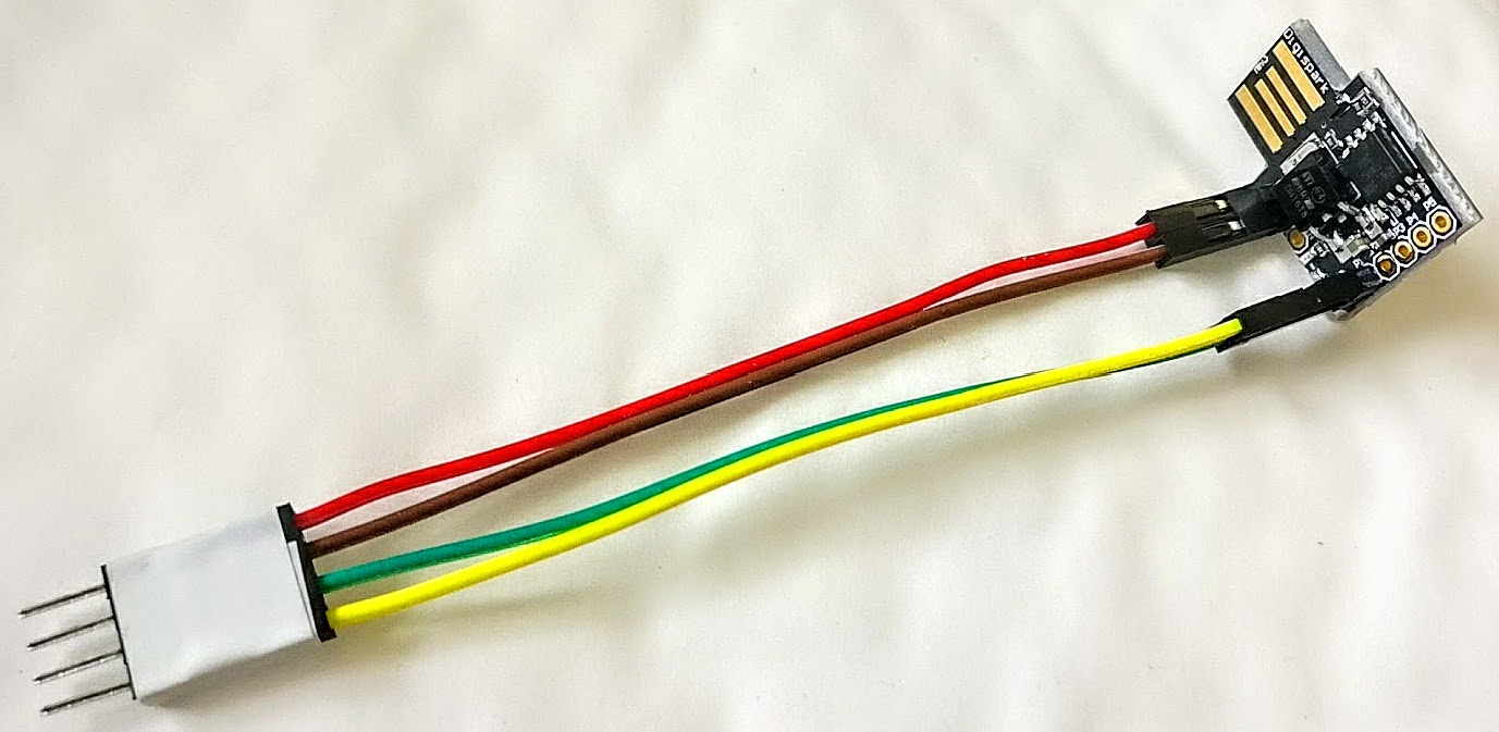
DigiSpark based board-tester for QC of RasPiO InsPiRing boards
It’s the same device I sent to the manufacturers for their QC testing because it is small, cheap, pretty bullet-proof and I would not have to explain to them how to use a Pi (which would also need a screen, keyboard, mouse etc. thus making everything much more bulky and complicated).
The next day, I tried the manufacturing trial boards on a Pi with the InsPiRing driver board.
I was quite surprised (in a rather bad way) when they didn’t work properly.
A close look at the LEDs showed they look a bit different from the SK9822 that I bought for development work (these were specified in the order).
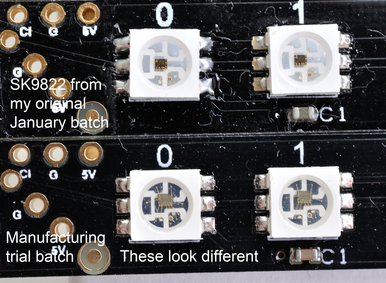
Original SK9822 (top), something a bit different (bottom)
You can clearly see that the die (chip) is larger on the manufacturing trial batch. It’s also a different colour and in a slightly different position. So are these different LEDs or has the manufacturer changed the spec on me? I wrote to my suppliers mentioning the issue and asking if they knew what might be the cause. I also sent them the above photo. In the meantime I did some investigations of my own.
Maybe I need a Software Tweak?
Because the LEDs looked different, I wondered if there needed to be a software tweak. I spent most of a day trying various software tweaks to my Python library, varying the bits and bytes sent over SPI.
I tried tweaking pretty much everything tweakable…
- adding extra null bytes
- removing null bytes
- changing null bytes to 1s
- sending SPI commands in a live Python session to see what happens
- even changing the SPI frequency in case the LEDs were ‘fussy’ about speed
- changed the Pi
- changed the driver board
- changed the LED board
I varied SPI frequency from 500 Hz all the way up to 20 MHz in small increments. Nothing changed for the better.
I thought it might be my software because I was using an Adafruit library on the DigiSpark, and FastLED on Arduino and Wemos. All these platforms worked perfectly well. So the obvious assumption was…
“It must be my software then – or the fact we’re using hardware SPI on the Pi”
I was getting pretty down about it, thinking the project in jeopardy, but knew the best thing I could do would be to put it on the oscilloscope and see what was happening.
Let’s have a Proper Look with the Oscilloscope!
I have a Rigol DS1054Z that I bought about 2 years ago. I haven’t used it an awful lot, but it’s a very nice ‘scope. I think it cost me slightly less than £300 GBP when I bought it.
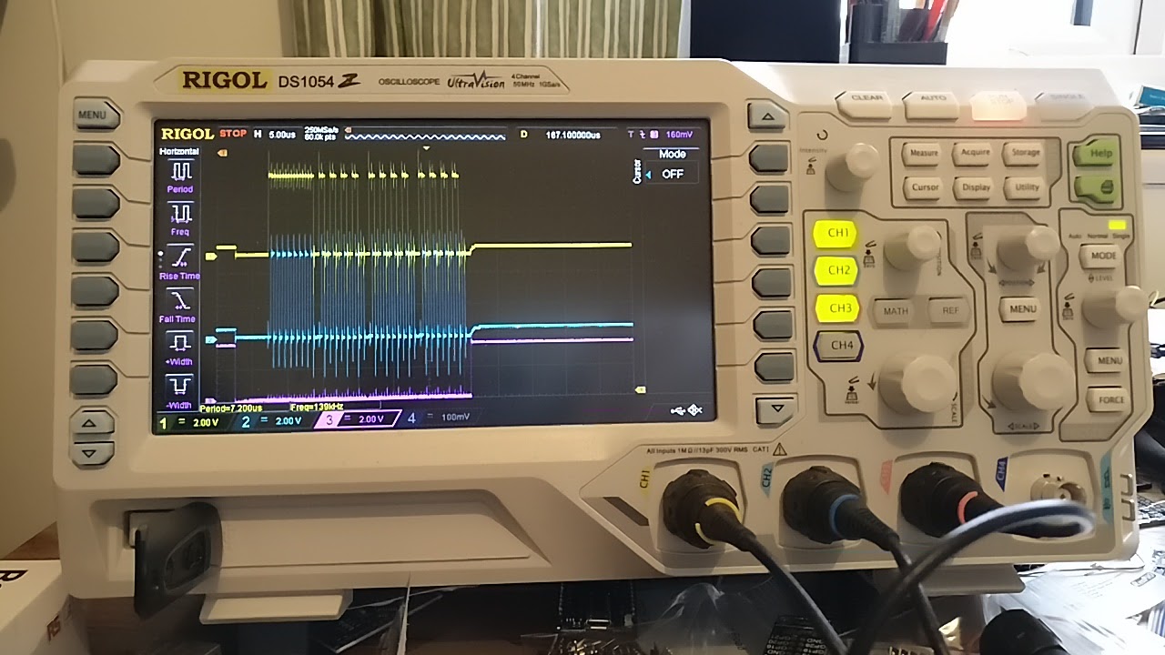
Rigol DS1054Z 4-channel oscilloscope
I decided that the best approach would be to ‘scope the MOSI and SCLK traces on a system that was working and compare those with the traces from the Pi. I happened to have a Wemos D1 mini with extra long pins. This made it ideal to hook up oscilloscope probes…
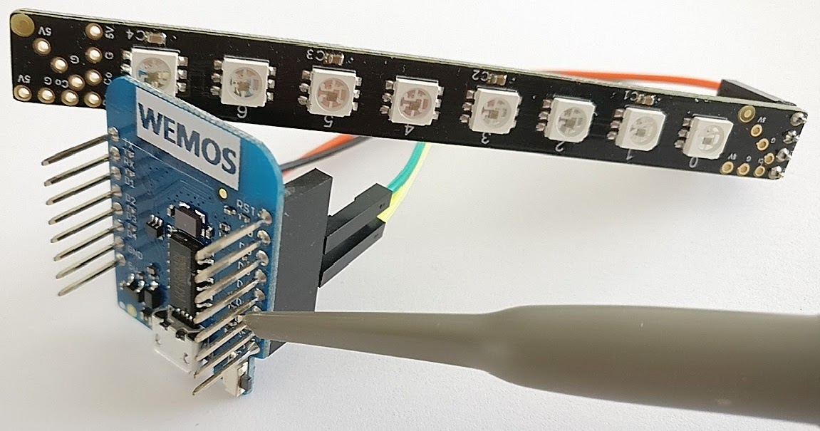
Long-pinned Wemos showing scope probe attachment
So I flashed a sketch to the D1 mini that would tell all 8 LEDs to light up 255 global brightness (11111111), 170 blue, 170 green, 170 red. Why 170? Well 170 is 10101010, which is a nice easy sequence to identify on an oscilloscope trace. Once I’d got the oscilloscope set up correctly, I obtained this trace…
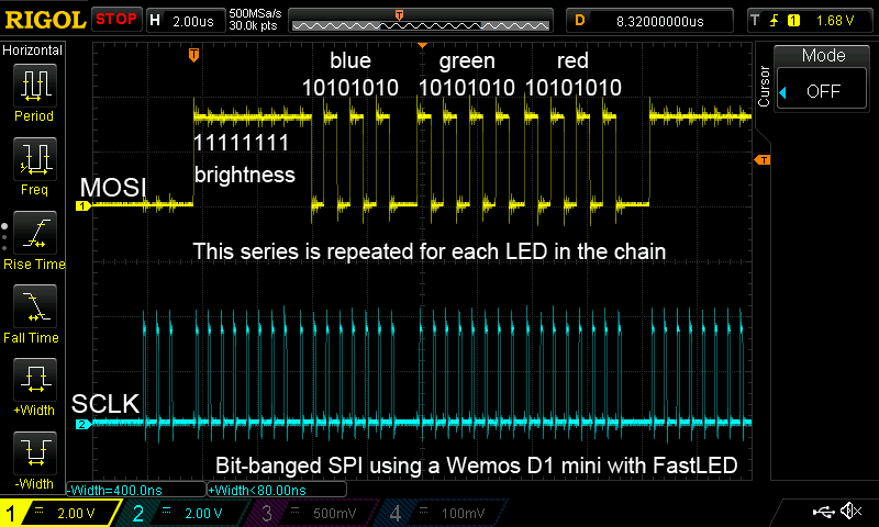
Wemos D1 mini driving RasPiO InsPiRing straight-8 production trial board
It clearly shows the sequence 11111111, 10101010, 10101010, 10101010 on MOSI (Master Out Slave In) which is the data line. The LEDs all lit up correctly as commanded. No surprise there. I already knew this was working. Now let’s ‘scope out what’s happening on the Pi (using an equivalent program written in Python). Because we’re using hardware SPI, I added an extra probe on the chip-select (CS) line to act as the oscilloscope trigger.
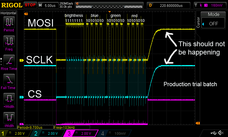
Raspberry Pi3 and InsPiRing driver board driving RasPiO InsPiRing straight-8 production trial board
The LEDs did not light the way they should have! And this ‘scope trace didn’t look right to me at all. OK the signals are being sent, but what the heck is that upward slope on both MOSI and SCLK after the 11111111, 10101010, 10101010, 10101010 sequence? It looked like it shouldn’t be there, but, just to be sure, I also measured one of the prototype boards I made with known good SK9822 LEDs…
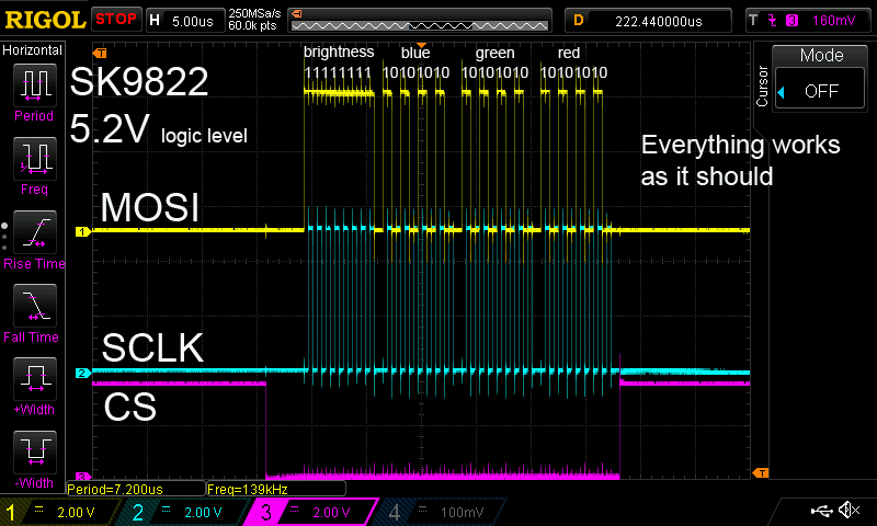
Raspberry Pi3 and InsPiRing driver board driving RasPiO InsPiRing straight-8 known good SK9822 board
This board worked perfectly and the ‘scope trace looks exactly as it should. There is no upward slope at the end.
So What’s Happening?
About this time, I got a reply from my manufacturers, which I paraphrase… “Yes you’re right the LEDs are different. Our buyer purchased APA102c instead of SK9822.”
There were two ‘aggravating’ (classic British understatement) things about this…
- This buyer originally suggested I change my design from APA102c to use SK9822 because of availability issues, which is why I bought a reel of 1000 from them back in January to do my prototyping
- SK9822 were specified in emails and on the Purchase Invoice
But OK. Getting over one’s irritation, let’s assume that they are APA102c and take stock.
- They work fine on a Wemos powered at 4.64V and using 3V3 logic level
- They work fine on a DigiSpark at 4.8V and using 4.8V logic level
- They don’t work on a Pi at 5.2V and using 5.2V logic (via the 74AHCT125N buffer chip)
According to the data sheet…

APA102c data sheet extract
…APA102c should work with a supply voltage of up to 6.0V (we’re using 5.2V – official Pi PSU) and an input voltage of up to 6.3V (we’re using 5.2V). So either they’re out of spec, the data sheet is wrong or they’re not what they claim to be. None of these is particularly good!
Whatever the reason, it looks like we may have an ‘out of spec voltage’ issue. Puzzling.
Now Let’s Have a Think
At this point, I’d at least managed to get my manufacturers to specify SK9822 for the rest of the project (the 900 straights yet to be made and the 700 each of the circles and triangles I had not yet ordered at that point. 900×8 + 700×24 + 700×24 = 40,800 LEDs in all). So although I was still not in the best place, at least I thought the project was back on track. PHEW!
But what about those ‘scope traces? Why on earth could that be happening?
Let’s assume the worst, that these LEDs are dodgy or out of spec. Is there anything that could be done?
Could I use resistors in a voltage divider to tweak down the Vin of the buffer chip to, say, 4.8V? Maybe that would work?
But those traces look almost like the MOSI and SCLK pins are somehow being ‘pulled up’ by the LEDs. Is it possible that, at 5.2V, the LEDs are overloaded? If so, what could be done?
And then it hit me – that Eureka moment which all scientists and engineers live for. That point where you overcome the world by the power of thought…
“I wonder what would happen if I added 10k pull-downs to the MOSI and SCLK outputs from the buffer chip?”
The reasoning behind this was that it looks as if, between pulses, MOSI and SCLK are being pulled up when they shouldn’t be (perhaps the tri-state logic on the 74AHCT125N chip leaves them floating when not ‘enabled’ via chip select? WJDK). So what if we were to pull them down to GND with hardware (resistors) to prevent this?
So I tried it. Guess what? IT WORKED! YAY! The LEDs did exactly what they should.
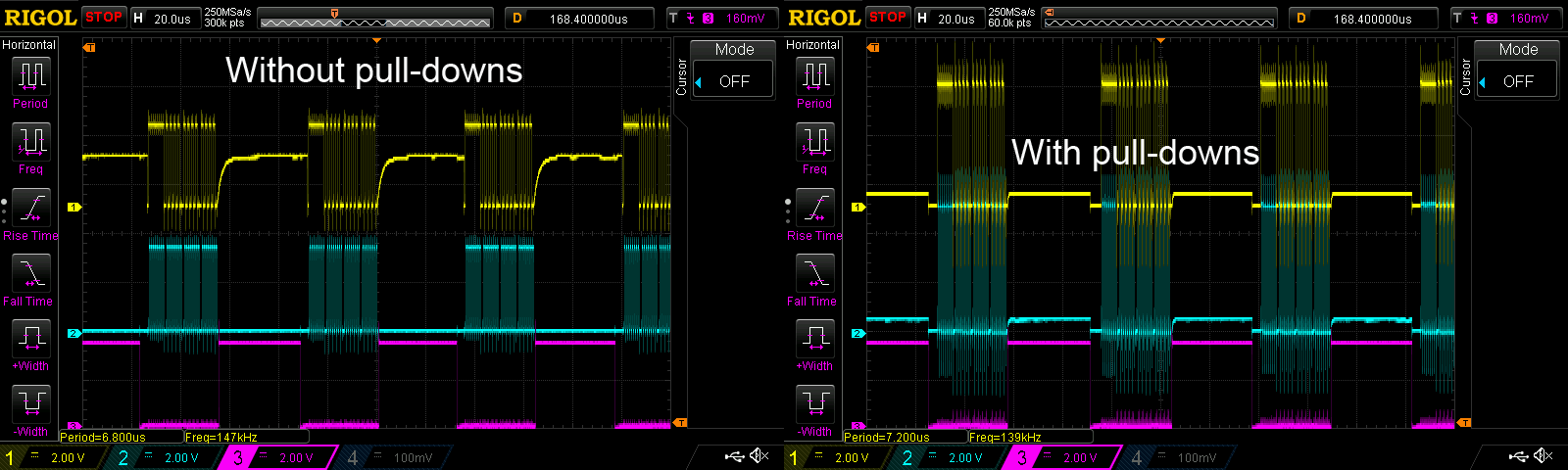
Without (left) and with (right) pulldowns on the ‘APA102c’ production trial boards
Looking at the ‘scope trace, the pull-downs prevent the voltage on MOSI and SCLK rising above 0.5V when they are inactive, which is enough to allow the ‘APA102c’ to be able to register a logical zero instead of being pulled high to 1 by whatever is causing that. It could well be ‘frowned on’, ‘poor SPI practice’, ‘not the done thing’ or just ‘really badTM‘, but what gave me a thrill was managing to think my way out of the problem. (All the more so since the engineers in China couldn’t think of anything that might help.) It works! So I tweeted about it…
Spent last 2 days diagnosing a problem. Solution is quite simple, but I'd not have found the issue without my oscilloscope. #PaidForItself pic.twitter.com/cIoLuRiRHg
— RasPi.TV (@RasPiTV) May 18, 2017
So as a result of this, all RasPiO InsPiRing driver boards will have two extra 10k resistors supplied in the kit in case anyone wants to drive ‘out of spec’ LEDs. I wouldn’t recommend fitting them routinely, but the option will be there for those who want to. (I love choices.)
What Did I Learn?
Lots actually…
1) I will be much quicker to get the ‘scope out next time. Once I stopped assuming it was my fault and used the proper diagnostic tool for the job, it became clear that something dodgy was happening and it wasn’t my software.
2) Oscilloscopes are amazing. I consider this ‘scope has paid for itself on this one diagnostic alone. Although I still lost two days to this problem, it could have been less if I’d got the ‘scope out earlier. But it also gave me the confidence to keep on with the project (and something interesting to blog about).
3) If you test something on one device it doesn’t automatically mean it will work on another. In an ideal world I would have had the LEDs tested on a Pi and driver, but that wasn’t really practical for this project.
4) Sometimes Chinese manufacturers will play ‘switcharoo’ on you and change a component. You need to keep your eyes open. This is one of the reasons why I like to do manufacturing trials, as it flushes out such things before it is too late to do anything about them.
5) Specify, specify and specify. At every stage of the process you need to give crystal clear instructions. The problem is that mistakes cost money. If things are correctly specified, at least you can argue your corner better when it comes to deciding who needs to pay for the mistakes.
Hopefully there won’t be any more scares like this on the InsPiRing project. I decided to blog about this because I thought it was really interesting and because I was very pleased that I managed to work out what was wrong and how to fix it. I hope you found it interesting too.
Nice one Alex, always good when you get a solution 😀
Alex, love your products and admire your engineering prowess, looking forward to getting mine, there’s an Analog Zero waiting to be assembled on my desk as I write this.. :-)
I’m not sure to understand the “out of spec” 5.2V is in the specs, the datasheet says that VCC have to be between -0.3V and 6V, and that the input voltage is min VSS-0.3, max VCC+0.3 so not 6+0.3 but 5.2+0.3.
So the input voltage have to be between -0.3 and 5.5V to not damage the chip, but it does not say that you are out of spec,
Power at 5.2V and IO at 3.3V is IN the spec, at least for that part.
The important information here are VIH and VLH: Input High voltage and Input Low Voltage
VIH is between 0.7*VCC and VCC + 0.3
VLK is between VSS-0.3 and 0.3*VCC
So to register a 0 you have to be between 0.3V and 1.56V, and for a 1 it is between 3.64V and 5.2V
So 5.2V for VCC and 5.2V for the input is correct.
The curve show that a capacitor is on the line MOSI/SCK (where? in the LED? hard to know)
It is also possible that the culprit is the PI itself, have you looked at driving the IOs without the LED plugged?
Maybe the Pi is pulling the IOs to 1 when unused, as when you normally use CS the chip is not reading the input so it don’t care about the state of MISO/SCK.
I highly suspect that the real culprit is the Pi, or how the SPI is configured on the Pi to be at a level High while idling.
You SPI bus is probably configured for Mode 2 or mode 3:
//—– SET SPI MODE —–
//SPI_MODE_0 (0,0) CPOL = 0, CPHA = 0, Clock idle low, data is clocked in on rising edge, output data (change) on falling edge
//SPI_MODE_1 (0,1) CPOL = 0, CPHA = 1, Clock idle low, data is clocked in on falling edge, output data (change) on rising edge
//SPI_MODE_2 (1,0) CPOL = 1, CPHA = 0, Clock idle high, data is clocked in on falling edge, output data (change) on rising edge
//SPI_MODE_3 (1,1) CPOL = 1, CPHA = 1, Clock idle high, data is clocked in on rising, edge output data (change) on falling edge
As shown here; http://www.raspberry-projects.com/pi/programming-in-c/spi/using-the-spi-interface
From the scope output, it is clocke on rising, so probably mode 3, you should try to change it to mode 0 (and if I’m wrong and it is on mode 2, try with mode 1)
Thanks for taking the time to comment :)
Exactly! My point is that the LEDs are not behaving correctly EVEN THOUGH the voltages I am using are WITHIN SPEC according to the data sheet.
I am saying that the LEDs are seemingly out of spec.
If you look at the evidence presented in the ‘scope traces for the SK9822 LEDs you can see that is not the case. The SK9822 LEDs work exactly as they should with exactly the same setup on the Pi and driver board. The ‘scope traces show that MOSI and SCLK are at zero when inactive. The ‘APA102c’ (if that’s what they are) are behaving out of spec.
There may be some sort of capacitance issue at work here, but the ONLY thing different between the two sets of traces is the LEDs themselves. So it’s definitely not the Pi. It’s likely to be something to do with how the LEDs themselves interact with the buffer chip.
Oh ok! It wasn’t clear about out/in spec part :-) And your are right, I miss read that part, and oversee the scope capture with the other type of LED…
I should repeat to myself: “Don’t answer when you head is not clear enough” ;-)
Ohhh!!! So you are using the /CS signal with the 74HCT125 /OE to put it in tri-state?
Then this is the reason, unlike i2c where the SCK and DATA are bidirectional are either grounded or tristated, SPI have each line with well defined direction, and SCK and MOSI are not meant to be tri-stated but set to an explicit ground or VCC.
And only a slave may have an tri-stated MISO output to allow the connection of more than one device on the same SPI bus.
As a SPI slave use high impedance input for the MOSI and SCK lines, by tri-stating the HCT125 you leave MOSI and SCK lines floating.
Now that make sense, as the line is floating any small leak from either side will put the line at a voltage which is somewhere between GND and VCC.
As I suppose you tristate the HC125 to have a chip select on the LEDs, so the SPI bus can be used for another one or something else depending on the CS (as the SK and APA don’t have a CS, that’s a pity) you have to pull up, or pull down both lines (the up or down) will depends on the SPI details, so in your case it is a pull down
But be careful as this problem can appear on both type of LEDs, even if probably the APA102 have an HiZ input design which seems to be more prone to current leaks than the SK9822, but on one silicon batch to another you may have enough variation that make one type to fail where it wasn’t before.
I would recommend to always put the pull down as long as the HCT125 is tri-stated for MOSI and SCK
Yes – you’ve got it. I want to be able to use MOSI and SCLK on the other Pi chip select line. You’ve come to pretty much the same conclusion that I had. It shouldn’t be a problem though because I will be supplying the pull-down resistors with every kit and showing people how to fit them.
Thanks for the extra info though. It all helps me to put together a fuller picture of what’s going on :)
Good luck with preparing all the kit, I can’t wait to receive mine :)
okay, learnt something here,
I always use my MCU with apa102c and direct lithium battery powering, and no issues before
could met the same in the future if I use higher voltages?