RGB LED RIP :(
Last week, I was wiring up a demo with a three colour RGB LED, and accidentally wired the pin for the red component straight to 3V3 (plugged it into the wrong port). It went “crackle” and then turned black. Ooops. Now it’s a GB LED, the red’s a gonner. :(
“Dammit. I wanted to shoot a video with the Quick2Wire Interface running the RGB LED. It’s 7pm and if I order some they won’t be here for two days.”
“Oh I know. I’ve got an RGB LED in an old Christmas present that doesn’t work properly any more. I wonder if I can remove it and use that?”
So I took it out, desoldered it, added some longer pins and…
…it didn’t work. Oh **************. :(:(
Looking at it from the other way
After a few minutes I thought to try it on reverse polarity – just in case. The original had a common cathode (-ve electrode), so each colour had a separate anode (+ve electrode – a for add, +). This one was the opposite.
That’s nice, but now my demo won’t work because I have a positive signal from the GPIO ports and (light emitting) diodes only work one way round.
Darlington to the rescue
Then I remembered something I learned when I was working with relays and using the Darlington array chip. What it does is, when there’s a positive input on the left side of the chip, it connects the right side of the chip to negative. Bingo – we’ve got the makings of a voltage inverter to drive our reverse polarity LED. ;)
(Of course you could always make a real voltage inverter using an op-amp, but this is simpler and multi-channel).
It makes things a bit more complicated than they needed to be for the “correct” polarity LED, but it helped me to get my video shot when I needed it. It helped me get the job done and didn’t take very long. And that’s a “result” in my view. :)
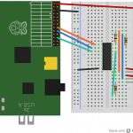
This is more or less what the circuit looks like.

Circuit diagram – use Darlington Array to control common anode rgb led.
I didn’t know how to stretch the resistor wires in Fritzing, so added other wires (which I haven’t really used) to make the connections. The photo shows what the real life circuit looks like. Resistor values were red = 68 Ohm, green = 6 Ohm, blue = 6 Ohm.
The photo shows what it really looked like attached to the Quick2Wire board I was testing. It’s the other way round from the Fritzing diagram.

The real circuit
I hope this idea helps someone. It certainly got me out of a hole.
Thanks a lot for sharing such a helpful article. Appreciate your efforts it helped me to use my spare Com Anode RGB LEDs with raspberry pi…..
Thanks
Brij
Excellent. Glad it helped you :) If you want to get really sophisticated, try the RPi.GPIO PWM. With RGB you should be able to generate any colour you want.
https://raspi.tv/2013/rpi-gpio-0-5-2a-now-has-software-pwm-how-to-use-it