Pi Supply is an external power switch for your Raspberry Pi. I have to be scrupulously honest here and say that, when I first heard about it, I thought “well that solves a problem I haven’t got”. But in the Raspberry Pi forums, quite a lot of people complained about not having a power switch. It’s never been an issue for me. I don’t find unplugging a micro USB cable all that hard. I’ve never broken the capacitor off the Pi (although I have broken a couple of SD card slots and fried a couple of SPI ports).
But, recently, I built Jason Barnett’s MotorPiTX board, which has a similar, but different, ATX-style power switch. I found myself rather liking it.
So when Aaron Shaw, a MagPi editor and the guy behind the Pi Supply switch, sent me some review samples of his products, I was already a lot warmer to the idea than I had been in the past.
Kit Contents
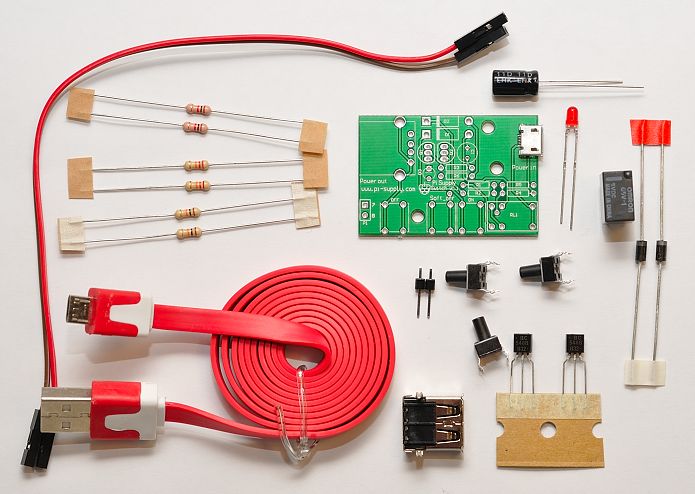
Here’s what you get in the kit…
The micro-usb port is pre-soldered. This is a nice touch because they’re quite fine pitch and really not that easy to solder well by hand. Aside from that you get…
- 6 resistors
- 2 diodes
- an electrolytic capacitor
- 2 transistors
- a small red LED
- 3 ‘tall’ buttons
- a 2 pin header
- an USB port
- a teeny relay
- a USB to micro-USB noodle cable
- 2 female-female jumper cables
- PCB with micro-USB
20 minute assembly
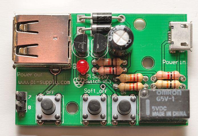
It took me about 20-30 minutes to put together. As usual, I was fussy to get everything straight and all the resistors the same way round etc. It looks better for the photos. Start with the lowest parts and build upwards. I did resistors first, then diodes, then LED, then transistors, electrolytic cap, USB port, header, buttons and then relay last.
It’s quite tightly packed, which gives you a small form factor.
What do the control buttons do?
You’ve got three control buttons. From left to right, they are…
- Power OFF – hardware kill switch
- Soft OFF – software shutdown – requires 2 wires to pins 7 & 8 and a program to be running
- Power ON
Buttons 1 & 3 work independently of what’s happening on the Pi. You can use these as simple OFF and ON switches.
Button 2, the “shutdown” switch, is designed to work with 2 jumper wires (provided in the kit) connected to pins 7 and 8 on the P1 GPIO header of the Pi. Pressing this button initiates a shutown on the Pi. Depending on which script you run, you may have to hold it for a second.
Two example Python scripts to use with this can be found here.
Can I still shutdown “normally”?
Yes. If you shut down your Pi the “normal” way e.g. by typing sudo halt, or sudo shutdown -h now, after about a minute, the capacitor is discharged and the relay opens, isolating the power. You’ll hear the relay click and see the red LED on the Pi extinguish.
How Much and Where?
The Pi Supply costs £15 and you can buy one from the Pi Supply shop
Do I need one?
It’s one of those little extra items that is really nice to have, but not essential (for me at least). But we all have different uses for our Pis, and for many people, this seems to be a ‘must-have’ item.
It’s definitely a nice little board and it works well so far. I think I might envelop mine in some clear heat-shrink to protect the underside from shorting if I put it down on something conductive. You could also mount it on some sort of backing, as mount holes are provided.


I was going to make one of these but do it as a GPIO daughter board (with a GPIO passthrough so you can still use the GPIO) and feed the power in through the GPIO inputs. That way you eliminate the USB cable and GPIO lead.
That sounds elegant Daniel. There must be a lot of different ways to do it.
I like the teeny little relay on this board. I wonder if it could be done with a power FET or something solid-state? (just to eliminate moving parts).
There is something nice about an off click from a relay though isn’t there ;)
Yes, that’s true.
I would use something like this, although this one seems just a touch pricey.
I would guess that you mostly use your Pis in situations where you’re logged into them by one means or another. In a stand-alone application, however, it is useful to have a shutdown button to ensure you don’t pull the plug while it’s writing to the sd card. If it’s going to shut itself down then it might as well disconnect the power, too – otherwise you’re left wondering how long to leave it before you pull the plug out. And if you’ve got an auto off function then it makes sense to switch it on in a similar fashion. It is also consistent with how many other modern devices are operated.
I tell you what I would pay for. A board with a built in rechargeable battery which gracefully shuts the Pi down when the power was pulled and recharges its built in battery when the power is connected.
That’s something else I’ve thought about. (I confess I do a lot more thinking than actual doing.)
The battery wouldn’t need to be very big but you would need some sort of charging control, and a regulator to feed the Pi since you don’t get 5v batteries.
If you want to run off a battery (3.6V) take a look at the work being done on the Beaglebone. Especially the mods that run the 5V USB from a 3.6V rechargeable battery:
http://pansenti.wordpress.com/2013/06/01/battery-powered-beaglebone-black-and-the-usb-host-port-works-too/
older post:
http://pansenti.wordpress.com/2013/06/01/powering-a-beaglebone-black-with-a-single-cell-li-ion-or-lipo-battery-yes-it-can-be-done-but-there-are-issues/
The benefit would be that you could just pull the plug or switch off at the mains without scrambling anything.
Exactly…
Most of the software and the circuit is really simple except the charging circuit.
Why not use a smartphone battery (as they almost all charge from micro USB, 5v standard) and a daughter board readily available for £3 on ebay (just search 5v lithium battery, brings up hundreds of the wee buggers) the smartphone battery and the board could easily be crafted into an elegant case alongside the Pi :)
Do you mean a USB power pack?
Yeah that might be a good starting point.
https://raspi.tv/2013/pi-duration-tests-and-review-of-two-new-lithium-battery-packs
;-)
I’m planning to combine it with something like https://raspi.tv/2013/controlled-shutdown-duration-test-of-pi-model-a-with-2-cell-lipo so that I can “gracefully shutdown” the Pi before the power-pack auto-cuts-out (the small battery pack gives you no ‘low power’ warning), but I haven’t got round to the electronics yet… need to find a spare weekend!
If this came with a decent 5V 2A supply the price would be very reasonable.
As an alternative for about the same cost you could use the RemotePi Board, which allows the use of an infrared remote control to switch power of the Raspberry Pi in addition to a pushbutton.
How do I make the script run if I have other script running on boot? Perhaps is there a way to make it work without adding the script into my “Primary” program like your RasPiCamcorder?
Thanks
It does NOT work!
I soldered everything following your instructions but when i press “soft OFF” button, it sends signal to GPIO 7 (forth line on the left) but never cuts off the power. If i try to press OFF button it cuts off the power correctly and ON button turns on everything.
In my opinion there is something wrong with diode D2, it avoids to put the capacitor to ground.
PS: what’s the reason to connect to GPIO 8 (aka UARD TXD) ?
I didn’t even try the ‘soft off’ for my review, so I’m not quite sure where you’re coming from with that comment.
I believe you have to follow the instructions from Pi-Supply and have a python program running in the background for the ‘soft off’ to work.
Your comment seems to think that this is my product. It isn’t! The above blog post is a review.
I had no intention to say it your product or your fault… just explaining my problem looking for a solution.
OK fair enough. Your wording was exactly as if you were addressing the manufacturer of the product. I just wanted to be clear that you knew it wasn’t me. :)
I don’t have a pi-supply myself, but I believe the pin 8 connection (you need to be careful with your terminology – pin 8 is different to GPIO 8 – see http://elinux.org/Rpi_Low-level_peripherals ) is used by the pi-supply to detect that the Pi has finished doing its “safe shutdown”, so it’s now safe to cut off the power (with no danger of causing SD card corruption).
Hello, 1Aug15
How much work would it be to add a clock to this?
It would allow my RP2 to auto-start everyday. Run a job and shut itself down. That would be fantastic!!
Eric.
why is the power out bigger
a) having the power-in and power-out be different sizes, prevents you connecting the cables the wrong way round ;)
b) at the time the PiSupply switch was designed, USB cables with a full-size on one end and a micro on the other end, were the only kinds of micro-USB cables commonly available
My first test of the switch seemed to be ok for on and off but not soft stop. The red led does not illuminate. I see on the handbook chat that someone has got the schematic an parts layout from somewhere. I would like a copy of the schematic to assist diagnosis
I don’t have one of these switches myself, but my first guess would be that the software hasn’t been updated for Raspbian Stretch?
https://github.com/PiSupply/Pi-Supply-Switch would be the best place to ask for help…
Can I also use it for Google Coral Dev Board?