
Giving GPIO Zero (Beta version) a test drive might make you feel a little insecure, but I’m aiming to throw some light on the situation. I decided to try out some of the built-in features of GPIO Zero by working up a little hardware project. I looked at the current feature set and decided to try and combine MotionSensor, LED and LightSensor all at once. What sort of project uses that kind of technology? Why a PIR-controlled security light of course – if you swap the LED for a relay and 12V lamp! The video will give you an overview of what’s going on. If you want to have a go at something similar, or find out how I did it, read on after the video…
Installation
If you are using a reasonably up-to-date Raspbian, you shouldn’t need to install anything as it will already be there. (Instructions left “struck out” for completeness.)
On a brand new Raspbian Jessie install, I first updated/upgraded…
sudo apt-get update

sudo apt-get upgrade
Then started to install GPIO zero with…
sudo pip install gpiozero

sudo pip-3.2 install gpiozero
The SPI driver ‘spidev’ install failed to begin with. This was cured by installing python-dev, which is often needed when you are compiling/installing python software that isn’t via ‘apt-get’…
sudo apt-get install python-dev python3-dev
…then I removed GPIO Zero and reinstalled it again…
sudo pip uninstall gpiozero

sudo pip install gpiozero
…and thereafter it worked perfectly.
Don’t forget this is a Beta release and future releases will be part of Raspbian. So when it’s a finely polished package, this will be a non-issue.
OK. So now we have GPIO Zero installed, we’ll need to wire up our circuit and write some code. Let’s do the circuit next, then the code.
Circuit Diagram
Here’s what the circuit looks like…
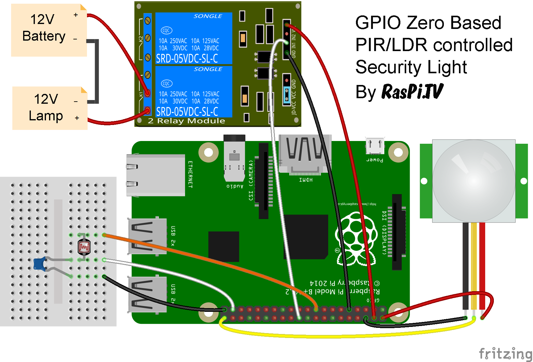
Circuit for GPIO Zero PIR/LDR 12V Security Light
Python Code
And here’s the Python code…
# This is a gpiozero test. We're going to make a PIR triggered
# security light
# There's a PIR sensor on GPIO21
# a relay on GPIO25 to switch  power to the 12V lamp
# and an LDR on GPIO26

from gpiozero import LED, MotionSensor, LightSensor
from time import sleep
pir = MotionSensor(21, queue_len=1)
light = LED(25)
ldr = LightSensor(26, queue_len=1)
light.off()
while True:
    if ldr.wait_for_dark():
        pir.when_motion = light.on
        pir.when_no_motion = light.off
        print("dark")
    if ldr.wait_for_light():
        pir.when_motion = light.off
        pir.when_no_motion = light.off
        print("light")
    sleep(0.2)
Code Walk-through
Lines 1-6 are comments
Lines 7-8 we are importing the functions that we need to use from the gpiozero and time modules
Lines 9-11 set up the MotionSensor, LED (relay-controlled light in our case) & LightSensor. I’ve used queue_len=1 to get a quicker response from the sensors. It prevents ‘averaging’ of the sensor output, by forcing it to average just one reading. For MotionSensor, the default has now been changed to 1 for future releases, so this can be omitted.
Line 12 we switch off the light to begin with because we’ve wired it up ‘backwards’ to get round the relay’s inverted logic (explained in more detail below).
Lines 13-22 contain our main program loop that carries on for ever.
Lines 14-17 if it detects a change from light to dark (14), it turns the light off if no motion is detected (15), and on if motion is detected (16), then it prints out “dark” on the screen (17).
Lines 18-21 if it detects a change from dark to light (18), it turns the light off if no motion is detected (19), and also off if motion is detected (20) – it’s daylight, so we don’t need a security light to come on, then it prints out “light” on the screen (21).
Line 22 Causes a 0.2 second pause before we start the loop again.
How Well Does It Work?
This program currently works fine, but when you try to exit it with CTRL+C it refuses to die. (You can kill it from another terminal window using top, k, type in the Python process number and then 15 then q to exit top). If I had to guess, I’d say it could be something to do with lines 14 and 18 both running repeatedly every 0.2 seconds. (I know, I’m a code vandal.)
The only other ‘issue’ with it is that I’ve used the LED class for a relay. The relay boards I’m using have inverted logic. So the switch is closed (ON) when GPIO25 is 0/LOW/False. You can get round this in two ways…
- Invert your program logic, so tell it
light.off()when you want the light to be on. This works well, but is rather confusing to read - Wire up the relay connection ‘backwards’ so that the power to the lamp is connected to the ‘NC’ (normally closed) terminal. This enables you to code in the most logical way, but the downside is that your lamp will be powered up the moment you connect its power supply, and won’t power down until you tell it
light.off()in line 12
Normally you would wire up a relay the other way round. But in this case, having tried both aproaches, I favour option 2 – code readability. After all, that’s what GPIO Zero is all about. The ideal solution will be to create a ‘relay’ class in GPIO Zero which will be a lot like the LED class, but with inverted logic.
Obviously if this is done, it will need to have warnings about what sort of electricity NOT to use. I’m using a battery powered 12V lamp here. You should not under any circumstances use bare relays like these to switch mains electricity at high voltage unless you know exactly what you are doing. (Basically DON’T!)
But I digress into electrical safety. The main point is that we have here a 16-line program (ignoring the comment lines) that provides all the logic and control needed to mimic a security light like the ones you probably have outside your house. It’s quite likely that I have horribly abused the system in my attempts to test three aspects at once. But that’s what Beta testing is all about. If everybody always did everything the way the author(s) expected, there would be very few bugs found.
So How Could We Take It Further?
No matter how much you do, it’s always possible to go further. One possible idea would be to make use of the mcp3008 class and add an analog to digital converter (ADC). Then we could read the light sensor (LDR) in a more sophisticated way and possibly even add some analog sensors.
You could also add some code to check the time (if the Pi is internet connected) and only activate during certain times. You could even use it as a time-switch to switch on the light if it’s dark and a certain time.
Summing Up
I enjoyed hacking around with GPIO Zero. As an experienced RPi.GPIO user I sometimes found Zero’s constraints a little restrictive (trying to do multiple things at once, in Beta), but that’s what you trade for being able to do so much with so few lines of code.
That’s the big attraction of GPIO Zero though. The fact that you can get going with just a few lines. For most people, this will outweigh the reduced flexibility. But if you need the flexibility, just ‘pop the hood’ and use RPi.GPIO, which is currently more suitable for advanced GPIO hackery.
As an exercise in fun, I might now go and see how many lines it takes me to reproduce this functionality in RPi.GPIO. I’ll see if I get time to do it.
Post-publication edit to add…
Dave Jones, who’s been working on GPIO Zero with Ben, has managed to get an alternative version of this script together in 15 lines (and it’s more elegant than mine). It works well and you can CTRL+C out of it too…
@RasPiTV 15 lines with no (obvious) loops? https://t.co/7HnbM6y1gU
— Dave Jones (@waveform80) October 15, 2015
from gpiozero import LED, MotionSensor, LightSensor
from signal import pause
pir = MotionSensor(21)
ldr = LightSensor(26)
light = LED(25)
def daytime():
    pir.when_motion = None
    pir.when_no_motion = None
    light.off()
def nighttime():
    pir.when_motion = light.on
    pir.when_no_motion = light.off
ldr.when_light = daytime
ldr.when_dark = nighttime
pause()
From GPIO Zero to Zero GPIO
If you want to be a real smartie-pants, you could point out that this can be done without a Pi or GPIO at all. We know this. After all, most PIR security lights have no Pi in. But, with a Pi controlling it you could send an alarm email/SMS/trigger a buzzer if the light comes on. And anyway, it’s fun and educational, so who cares? But my friend Daniel challenged me to reproduce this in ‘hardware only’, so I have. Here it is…
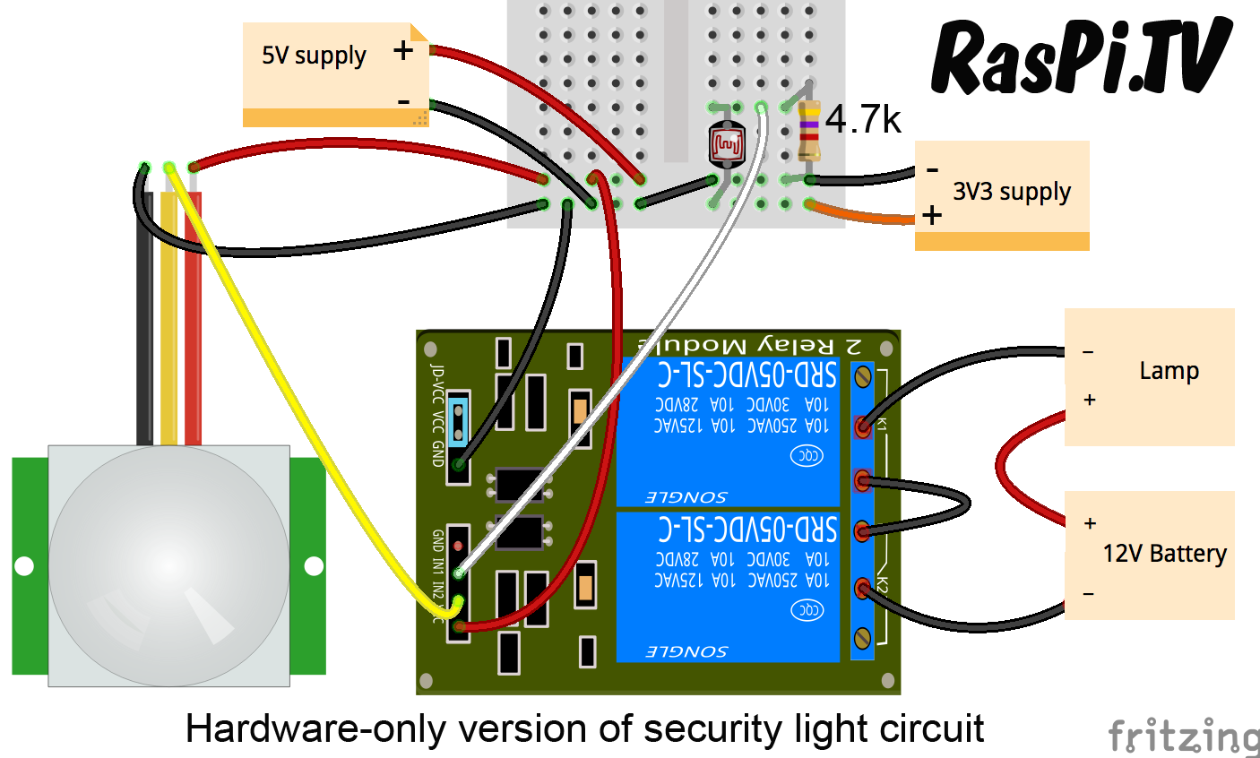
Security light circuit in hardware only. Zero lines of code.
The hardest part was finding a resistor value that worked to trigger the relay whilst balancing the LDR properly. In the end, 4.7k proved to be the optimum (no equations, just 2 or 3 iterations of ‘see if this one works’). Note also that the second relay (K2) has been wired ‘backwards’ to invert the logic of the PIR output for us.
What size capacitor did you use in the first circuit?
100 nF
“sudo pip install gpiozero”
and
“sudo pip-3.2 install gpiozero”
both return a “sudo: pip: command not found”
and “sudo: pip-3.2: command not found”
What do I do?
Actually if you’re using a Raspbian from November 2015 or later, gpiozero will already be onboard. Otherwise you’ll need to install python-pip first
Yes, I didn’t have pip installed and didn’t know what it was. Thanks.
Hi
How to add a command to the suspension of the lamp, for example half a minute after the same motion ?
Thank you
Yoel
Hi i’m new in python
I want to add a command line:
When there is a motion in dark the LED stay on for one minute
I’ve not tested it (you get that fun for yourself!) but something like this might work after Alex fixes the indentation…
(I’ve assumed what you *actually* want is for the LED to stay on for one minute after the motion stops, rather than always turning the LED off one minute after motion was first detected? A subtle but important difference if the motion itself lasts for more than one minute!)
from gpiozero import LED, MotionSensor, LightSensor from threading import Timer from signal import pause pir = MotionSensor(21) ldr = LightSensor(26) light = LED(25) off_timer = None def cancel_timer(): global off_timer if off_timer is not None: off_timer.cancel() off_timer = None def motion_func(): cancel_timer() # new motion detected, so we don't want the light turning off yet light.on() def no_motion_func(): cancel_timer() # cancel the old timer because we're about to create a new one global off_timer off_timer = Timer(60, light.off) # turn the light off after 60 seconds off_timer.start() def daytime(): pir.when_motion = None pir.when_no_motion = None cancel_timer() # we're about to turn the light off anyway light.off() def nighttime(): pir.when_motion = motion_func pir.when_no_motion = no_motion_func ldr.when_light = daytime ldr.when_dark = nighttime pause()Thanks AndrewS for the comment
But the code you wrote is not working (No error message) Nothing is happening
Thanks
Thank you for posting this I’m new to the world of Raspberry so using this page to find interesting projects to do as I learn. I plan to use this in an outdoors shed to light it as I get my bike out at 4am. This code works fine for me I’ve even managed to get it to load and work automatically when the Raspberry boots, however when the light comes on the ldr senses it’s no longer dark so the light turns off am I missing something or is there a way to stop this from happening by adding to the code?
Might be easier to move or ‘shield’ the LDR, so that it can’t ‘see’ your light?
But yes, you could fix it in code if you just re-arrange the logic slightly… (left as an exercise for the reader – solving problems like this is what makes coding fun!)
Absolutely nothing works for me. I can’t even get a light to come on. I have an LED wired onto pin 25 and nothing else.
Script:
from gpiozero import LED
light = LED(25)
light.on()
This just yields a massive screed of error messages. When I put the code in through the shell, the errors come up for the “light = LED(25)” line. What’s going on? Nobody online has a solution.
Just in case you didn’t notice – GpioZero uses ‘BCM’ pin numbering, not physical pin numbering http://gpiozero.readthedocs.io/en/v1.2.0/recipes.html#pin-numbering
And if you’re connecting an LED to a pin, you need to make sure you use a current-limiting resistor, otherwise you might damage the LED and / or your Pi. See http://gpiozero.readthedocs.io/en/v1.2.0/recipes.html#led or https://raspi.tv/2013/rpi-gpio-basics-5-setting-up-and-using-outputs-with-rpi-gpio for examples.
Can you copy’n’paste your errors somewhere? Bit hard to tell what’s going wrong otherwise…
Will this work on the pi zero?
Yes. As far as basic GPIO stuff like this is concerned, the Pi Zero is essentially the same as any other 40-pin Pi
Hello. Thanks for this and all your videos. They are very helpful.
I realize it is unlikely you would still be reading these comments this long after posting but just in case I will ask my question.
What is the battery being used in the video? I have application that will not have access to mains power and I cannot find a good battery solution. I need 12v and normal 12v batteries are basically car batteries, expensive, large and super heavy. I found battery cases that can take 8 AA batteries together to make 12v but it seems kind of flimsy. The battery in the video is small, but seems more together and integrated than a battery holder. Would love to know more about what it is.
Thanks.
It’s a 3 cell lipo (2200 mAh). Lithium polymer battery, as used in model aircraft and lots of things these days. They need dedicated chargers and special handling though.
If you want something less bulky than a car battery, but more robust than a stack of AAs, you could have a look at the options here:
http://www.maplin.co.uk/c/batteries-and-power/specialist-batteries/sealed-lead-acid-batteries
Batteries *always* come down to a trade-off of size (and weight) vs. capacity (i.e. runtime).
Thank you both for responding.
I got myself an expensive special charger for lithium polymer batteries. Got talked into buying it for a different project some time back. Was under the impression that all the LiPo cells were always 3.7v. Three times 3.7 is 11.1. Is that voltage assumption wrong or is 11.1 close enough to 12v to make the light work in the video?
Andrew, that was an excellent suggestion, thank you. I did not see anywhere lead acid batteries that were that price range and/or size. Maybe I need to live in the UK. :-) Even though they have a low capacity I do not need much in the way of capacity for operating my 12v device in this case. (It is 12v solenoid lock that only needs to be able to go off a couple of times before the battery gets recharged.) So items like that may be just the thing.
Perhaps I am being overly cautious and should just do a stack of AAs, but I do feel like something more robust would be better so I appreciate you guys making those posts.
AFAIK a light is pretty much an `analogue` device, so it’ll work at any voltage, just less brightly – the closer the input voltage is to 12V, the closer the lamp will be to its maximum brightness.
Whether 11.1V is enough to fully-open your solenoid lock (you obviously don’t want it only opening half-way), you’ll only be able to discover by testing it yourself ;-)
Don’t forget that battery-discharge curves mean that no battery is guaranteed to give out it’s “rated” voltage when under load. If you need a “guaranteed” 12V (which you probably don’t – unless testing shows otherwise) you’d need to use a higher-voltage battery (or batteries in series) and a step-down converter.
I guess the other problem with a stack of AAs is that they’re more awkward to recharge than just a single unit.
Good luck with your project!
3.7 volts per cell is the nominal voltage for lipo. But when at rest and fully charged they are 4.2 V per cell.
AndrewS, thanks for the extra info. With many things in the world of computers and electronics you really do not know until you test it. I have been looking around more thanks to your suggestion and have found a wider variety of options and discovered Maker Batteries brand battery kits. Hopefully that project will get off the ground.
Alex, interesting, thanks. Knowing that gives me more to think about. And thanks for all the work you do putting together Raspi.TV.
Absolutely nothing works. I just get a string of errors.
Even something as simple as:
from gpiozero import LED
light = LED(25)
light.on
sleep(2)
Just brings up the exact same slew of errors.
If you tell us what the errors actually *say*, then we might be able to give you some hints on how to solve them… ;-)
Hello I have project of smart light .can you help me??