Today is output day. I’m going to show you how to switch things on and off using RPi.GPIO to control the output ports of the Raspberry Pi.
Once you can control outputs, you can, with a few additional electronic components, switch virtually anything on and off. Given the Raspberry Pi’s excellent connectivity, this means you can switch things on and off through the internet, using any computer, smartphone or tablet from anywhere in the world. You can also use a local network, Bluetooth etc. for short-range control.
Setting up is very similar to the way we set things up for inputs, but instead of…
GPIO.setup(port_or_pin, GPIO.IN)
we use…
GPIO.setup(port_or_pin, GPIO.OUT)
Then, to switch the port/pin to 3.3V (equals 1/GPIO.HIGH/True)…
GPIO.output(port_or_pin, 1)
Or, to switch the port/pin to 0V (equals 0/GPIO.LOW/False)…
GPIO.output(port_or_pin, 0)
How to set an output – full Python code
import RPi.GPIO as GPIO           # import RPi.GPIO module
GPIO.setmode(GPIO.BCM)            # choose BCM or BOARD
GPIO.setup(port_or_pin, GPIO.OUT) # set a port/pin as an output
GPIO.output(port_or_pin, 1)       # set port/pin value to 1/GPIO.HIGH/True
GPIO.output(port_or_pin, 0)       # set port/pin value to 0/GPIO.LOW/False
You can also set the initial value of the output at the time of setting up the port with initial=x optional extra argument…
GPIO.setup(port_or_pin, GPIO.OUT, initial=1)
or
GPIO.setup(port_or_pin, GPIO.OUT, initial=0)
And that’s really (almost) all there is to it. You can use GPIO.HIGH or GPIO.LOW and True or False as well, but I prefer 1 or 0 because it’s less keystrokes.
Working example
Let’s have a working example. We’ll set up RPi.GPIO in BCM mode, set GPIO24 as an output, and switch it on and off every half second until we CTRL+C exit.
import RPi.GPIO as GPIO            # import RPi.GPIO module
from time import sleep             # lets us have a delay
GPIO.setmode(GPIO.BCM)             # choose BCM or BOARD
GPIO.setup(24, GPIO.OUT)           # set GPIO24 as an output

try:
    while True:
        GPIO.output(24, 1)         # set GPIO24 to 1/GPIO.HIGH/True
        sleep(0.5)                 # wait half a second
        GPIO.output(24, 0)         # set GPIO24 to 0/GPIO.LOW/False
        sleep(0.5)                 # wait half a second

except KeyboardInterrupt:          # trap a CTRL+C keyboard interrupt
    GPIO.cleanup()                 # resets all GPIO ports used by this program
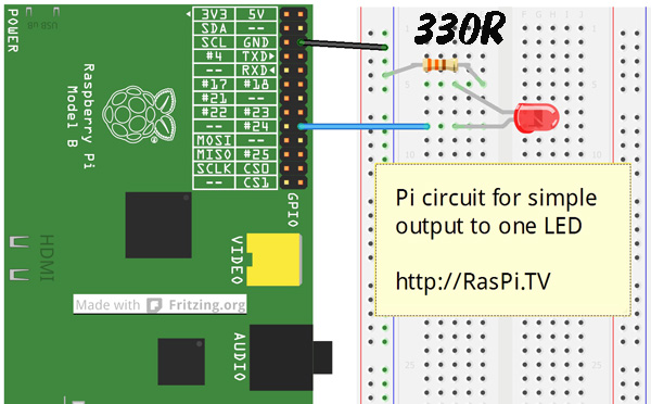
You can check this is working either by connecting a Voltmeter/oscilloscope to port 24 and GND or by using this circuit with a resistor (330R) and LED, which will flash on and off every half second. When you press CTRL+C to exit, the GPIO ports we used are reset.
Limit the current on the 3V3 supply
All the GPIO ports take their power from the Raspberry Pi’s 3.3V (3V3) supply. The maximum recommended current draw from that supply is 51 mA. This is the total for all the 3V3 GPIO pins.
This is more than enough for controlling logic gates and integrated circuits. But if you are running LEDs directly from the ports, it is possible to overload them. You need to be careful about this.
The maximum current draw from any one pin should not exceed 16 mA. Many LEDs can draw more current than this, so you need to choose a resistor value that limits the current to an acceptably safe value. (One of my favourite LED calculators can be found here.)
I chose 330 Ω (330R) for this example because it should be high enough to be safe for pretty much any LED you could choose. The LED might not be as bright as it would with a lower value resistor, but your Pi ports should be OK.
Generally speaking, you should use the GPIO ports to trigger/switch things rather than to power things. We’ll cover the use of a Darlington array chip, which helps you do this, in a later article.
How to read the status of an output pin
Sometimes, when using a port as an output, it might be useful to be able to “read” its status – whether it’s 1/GPIO.HIGH/True or 0/GPIO.LOW/False.
You can do this by treating it as an input port.
GPIO.input(24)
Let’s modify the LED script to read the status of GPIO24 (lines 10-11 & 14-15) and give us a message about the LED’s status. (This is a very simple and controlled example. You wouldn’t normally use it in this situation – I’m just showing you how.)
import RPi.GPIO as GPIO            # import RPi.GPIO module
from time import sleep             # lets us have a delay
GPIO.setmode(GPIO.BCM)             # choose BCM or BOARD
GPIO.setup(24, GPIO.OUT)           # set GPIO24 as an output

try:
    while True:
        GPIO.output(24, 1)         # set GPIO24 to 1/GPIO.HIGH/True
        sleep(0.5)                 # wait half a second
        if GPIO.input(24):
            print "LED just about to switch off"
        GPIO.output(24, 0)         # set GPIO24 to 0/GPIO.LOW/False
        sleep(0.5)                 # wait half a second
        if not GPIO.input(24):
            print "LED just about to switch on"
except KeyboardInterrupt:          # trap a CTRL+C keyboard interrupt
    GPIO.cleanup()                 # resets all GPIO ports used by this program
So now you know how to use RPi.GPIO to set up and control outputs on the Raspberry Pi.
In the series so far, we’ve covered…
- How to check what RPi.GPIO version you have
- How to check what Pi board Revision you have
- How to Exit GPIO programs cleanly, avoid warnings and protect your Pi
- Setting up RPi.GPIO, numbering systems and inputs
- Setting up and using outputs with RPi.GPIO
RasPiO® GPIO Reference Aids
Our sister site RasPiO has three really useful reference products for Raspberry Pi GPIO work...


[…] raspi.tv: Today is output day. I’m going to show you how to switch things on and off using RPi.GPIO to […]
What is the Python equivalent of this command from this gpio utility command ?
(taken from http://projects.drogon.net/raspberry-pi/wiringpi/the-gpio-utility/)
gpio [-g] mode up/down
While I can get around it, I want to do it the “right” way
..and thanks, got everything else working perfectly
Have a look at part 6… https://raspi.tv/2013/rpi-gpio-basics-6-using-inputs-and-outputs-together-with-rpi-gpio-pull-ups-and-pull-downs
I need to know how to control 10 GPIO with led do any body know the codes for that
Just duplicate the code above, replacing ’24’ with each of your GPIO numbers, e.g. if you had LEDs on GPIOs 23, 24 and 25, you could do:
import RPi.GPIO as GPIO
from time import sleep
GPIO.setmode(GPIO.BCM)
GPIO.setup(23, GPIO.OUT)
GPIO.setup(24, GPIO.OUT)
GPIO.setup(25, GPIO.OUT)

try:
    while True:
        GPIO.output(23, 1)
        GPIO.output(24, 1)
        GPIO.output(25, 1)
        sleep(0.5)
        GPIO.output(23, 0)
        GPIO.output(24, 0)
        GPIO.output(25, 0)
        sleep(0.5)

except KeyboardInterrupt:
    GPIO.cleanup()
As the meerkats say: Simples!
I tried with two and I get alternate lights, I don’t understand why. In my mind I supposed they will be on and off together
Sounds like this might be a wiring error? Double-check all your connections, and check your LEDs are the right way round.
How many of the pi pins can be set to output ?
26 on an A+, B+ or Pi 2 B
17 on the old A & B
Sorry I guess my question wasn’t well asked I want to control electrical outlets. Turning them on and off How many could I controll with one pi ?
The easiest (and safest!) way to control electrical outlets with the Pi is https://www.raspberrypi.org/blog/controlling-electrical-sockets-with-energenie-pi-mote/
I’m using a Raspberry Pi 3 and I was just wondering if it would be safe to directly power two 3V fans through the GPIO pins. Pins 37&39 being 3V power and pins 38&40 being ground. I am using a touch screen and it uses pins 1-26 so the power is inaccessible I am still learning so a reply would be much appreciated.
Definitely not. Firstly you should respect the current limit of 12 mA per port and secondly a fan motor will be an inductive load which will likely cause problems. In practice though it’s unlikely to be a problem because probably the motors simply will not run.