Well, today is the day we actually get to use RPi.GPIO a little bit. But, before we get to that, you should know about the two different numbering systems you can use with RPi.GPIO.
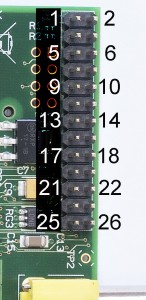
If you take a look at the main GPIO header (P1) of the Raspberry Pi, you’ll see that there are 26 pins. The top left pin (as we look at this photo) is called pin 1, the one to the right of it is pin 2. So the next row is 3, 4 etc. and on down to 25, 26. This is how pin headers are numbered.
But Pins have names too
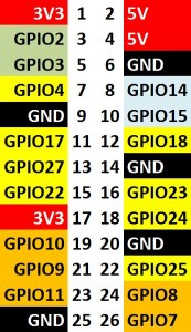
The slightly confusing part is that each pin also has a name, according to what it does. Some of them have alternative functions, but RPi.GPIO doesn’t currently control those, so we’ll ignore them for now. The best way to see which pin number does what is with a diagram…
- red ones are +ve power (3V3 or 5V)
- black ones are -ve ground
- yellow ones are all dedicated general purpose I/O ports (OK, 18 does PWM as well, but forget that for now).
The rest can all be used as GPIO ports, but do have other functions too. If you need 8 or less ports, it’s best to use the yellow ones because you’re less likely to have a conflict with other things. A quick rundown of what the others are…
- greeny/grey – i2c interface
- light grey – UART (serial port)
- orange – SPI (Serial Peripheral Interface)
How to set up BOARD and GPIO numbering schemes
In RPi.GPIO you can use either pin numbers (BOARD) or the Broadcom GPIO numbers (BCM), but you can only use one system in each program. I habitually use the GPIO numbers, but neither way is wrong. Both have advantages and disadvantages.
If you use pin numbers, you don’t have to bother about revision checking, as RPi.GPIO takes care of that for you. You still need to be aware of which pins you can and can’t use though, since some are power and GND.
If you use GPIO numbers, your scripts will make better sense if you use a Gertboard, which also uses GPIO numbering. If you want to use the P5 header for GPIO28-31, you have to use GPIO numbering. If you want to control the LED on a Pi camera board (GPIO5) you also have to use GPIO numbering.
The important thing is to pick the one that makes sense to you and use it. It’s also important to be aware of the other system in case you ever need to work on someone elses code.
So, at the top of every script, after importing the RPi.GPIO module, we set our GPIO numbering mode.
import RPi.GPIO as GPIO

# for GPIO numbering, choose BCM
GPIO.setmode(GPIO.BCM)

# or, for pin numbering, choose BOARD
GPIO.setmode(GPIO.BOARD)

# but you can't have both, so only use one!!!
So, with a drumroll and a fanfare of trumpets, it’s now time for us to set up some inputs.
How to set up a GPIO port as an input
Use the following line of code…
GPIO.setup(Port_or_pin, GPIO.IN)
…changing Port_or_pin to the number of the GPIO port or pin you want to use. I’m going to use the BCM GPIO numbering and port GPIO25, so it becomes…
GPIO.setup(25, GPIO.IN)
import RPi.GPIO as GPIO
GPIO.setmode(GPIO.BCM)  # set up BCM GPIO numbering
GPIO.setup(25, GPIO.IN) # set GPIO 25 as input
We’ve just set up port 25 as an input. Next we need to be able to “read” the input.
Reading inputs
Inputs are Boolean values: 1 or 0, GPIO.HIGH or GPIO.LOW, True or False (this corresponds to the voltage on the port: 0V=0 or 3.3V=1). You can read the value of a port with this code…
GPIO.input(25)
But it may be more useful to use it as part of your logic…
if GPIO.input(25): # if port 25 == 1
    print "Port 25 is 1/GPIO.HIGH/True"
…or store its value in a variable to use in a different part of the program…
button_press = GPIO.input(25)
So, building on what we’ve already done, here’s a very simple program to read and display the status of port 25, but it only does it once, then it cleans up and exits.
import RPi.GPIO as GPIO
GPIO.setmode(GPIO.BCM)       # set up BCM GPIO numbering
GPIO.setup(25, GPIO.IN)      # set GPIO 25 as input

if GPIO.input(25):           # if port 25 == 1
    print "Port 25 is 1/GPIO.HIGH/True"
else:
    print "Port 25 is 0/GPIO.LOW/False"

GPIO.cleanup()               # clean up after yourself
The above is not really complete yet, what we need to do is add…
- a loop, so we can make it read more than once
- a time delay, so it won’t read the port thousands of times per second
- a circuit with a button, so we can change the status of the port and see the input status change on the screen
- a try: except KeyboardInterrupt: block so we can exit cleanly (we covered this yesterday)
So, let’s make a little circuit
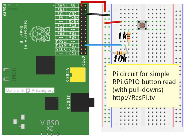
In order to go any further with this, we need to make up a little circuit.
The resistors are used to “pull down” the GPIO25 pin to 0 Volts GND (0V, 0, LOW, False) unless the button is pressed. When the button is pressed, GPIO25 is connected to 3.3V. If you don’t use the resistors, it might still work, but you risk having a “floating” port. It’s not dangerous, (it could be if you had something like a motor attached) but it’s not fully in control either. We’ll cover a bit more on floating ports, pull-ups and pull-downs in another article (probably part 6).
If you don’t have a breadboard, resistors and buttons, you could cheat and just use a jumper wire to connect two pins directly, but you’ll need to be aware of what you’re doing.
Here’s the code with all the extras added to read and display the button’s status, and exit cleanly when CTRL+C is pressed…
import RPi.GPIO as GPIO
from time import sleep     # this lets us have a time delay (see line 12)
GPIO.setmode(GPIO.BCM)     # set up BCM GPIO numbering
GPIO.setup(25, GPIO.IN)    # set GPIO 25 as input

try:
    while True:            # this will carry on until you hit CTRL+C
        if GPIO.input(25): # if port 25 == 1
            print "Port 25 is 1/GPIO.HIGH/True - button pressed"
        else:
            print "Port 25 is 0/GPIO.LOW/False - button not pressed"
        sleep(0.1)         # wait 0.1 seconds

except KeyboardInterrupt:
    GPIO.cleanup()         # clean up after yourself
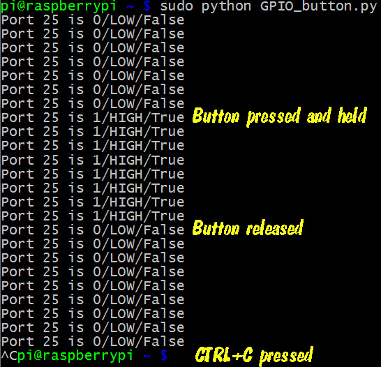
This is what the above program’s output looks like…
Polling loop
This program uses a polling loop. It checks (polls) the input port 10 times per second. It works well, but is not very efficient. A more efficient, and more advanced way to handle this is with interrupts. I’ve written about how you can use interrupts in RPi.GPIO here.
That was inputs with RPi.GPIO
So now you know how to use RPi.GPIO to set up and read the status of an input port. In part 5, we’ll cover Outputs.
A quick recap of what we’ve covered so far
So now we’ve covered…
- How to check what RPi.GPIO version you have
- How to check what Pi board Revision you have
- How to Exit GPIO programs cleanly, avoid warnings and protect your Pi
- Setting up RPi.GPIO, numbering systems and inputs
RasPiO® GPIO Reference Aids
Our sister site RasPiO has three really useful reference products for Raspberry Pi GPIO work...


[…] for instance. So far, he’s covered the basics and has now turned his attention to both inputs and […]
Strictly speaking, ground is 0V not a -ve voltage (although it does correspond to the -ve terminal on a battery).
Actually, there’s nothing stopping you from calling setmode() multiple times in the same program – you just need to remember whether you’re in BOARD or BCM mode whenever you call a function that has a Port_or_pin as an argument. So obviously it’s not recommended to switch between BOARD and BCM within the same program ;-)
Although if you do try to setup() a power or ground pin whilst using BOARD mode, RPi.GPIO will tell you you’ve chosen an invalid pin.
All that being said, I personally use BCM mode (i.e. raw GPIO numbers) too because it’s what I’m familiar with using on other embedded boards, and it matches the numbers in sysfs if I want to manipulate the GPIOs directly from the command line http://elinux.org/RPi_Low-level_peripherals#Bash_shell_script.2C_using_sysfs.2C_part_of_the_raspbian_operating_system
Alex, would it be worth including a “GPIO pinouts for Rev 1 Pi” for the sake of completeness? (with maybe a link to the low-level-peripherals wiki page for folks that want to “Read more”)
Looks like the Fritzing diagram is still using the Rev 1 pinout…
Apologies if I’m being too pedantic!
Don’t worry about the pedantry. I’ve tried to keep it simple and easy to understand.
Ref the Rev 1/2 & Fritzing, you may note I’ve only used pins which are the same in Rev 1 and Rev 2 for these experiments. I habitually do that to keep things simple and avoid confusion. GPIO24 & GPIO25 are the same on all Pis made so far.
The Fritzing Pi model I have won’t let me connect to any of the “DNC” pins either, (which are now GND)
Well that’s an unfortunate surprise – I’ve just downloaded the latest 0.8.0b version of Fritzing (I’ve never even used it before) and it seems it still only has the Rev1 Pi, even though it was released in June 2013 (i.e. well after the release of the Rev2 Pis themselves) :-/
And the “Schematic” tab shows GPIO0 -> GPIO7, which is even more weird!
Hmmm…. so I just went searching for updated Raspberry Pi Fritzing models, and found one from Binnery (which doesn’t have any pin-labels), and one from Adafruit, which has the same pin-labels as the model built-in to Fritzing, so I just submitted https://github.com/adafruit/Fritzing-Library/issues/14 :-)
Ooooh, although I now notice that you’re actually using the Adafruit Fritzing Pi model, and not the one built in to Fritzing. They’re almost the same though.
Just found and added a comment to http://code.google.com/p/fritzing/issues/detail?id=2080#c5 too ;)
Yep – using the Adafruit Pi model. It would be nice if it was up to date, but I don’t think it being slightly out of date detracts from its usefulness in this context. It’s surely much clearer to see what wiring to do than if I just wrote in words “connect a wire between GPIO25 and a 1k resistor” etc. :)
Oh, it’s definitely useful and much clearer than just text or even a photo would be! (sorry if I gave the wrong impression)
Just my programmer’s pedantism kicking in again ;-)
Programmers and Translators are the biggest pedants – along with Librarians, Lexicographers.
Editors not so much, they just change things to make them read badly or just plain wrong ;)
[…] Part 4: “setting up RPi.GPIO, numbering systems and input”: […]
Hi Alex
Congratulations on your excellent Input & Output tutorials – very nicely explained for someone well down the learning curve. I have decided to follow your lessons and got a shiny new B+ Pi and a Cyntech B+ Paddle. I noticed that on running the one-button polling program above, without anything attached to the Pi, I get the “button not pressed” message repeatedly. This is what I expected.
However, when I connect the Paddle to the Pi, again with nothing else attached, the program’s output changes back and forth between “button not pressed” and “button pressed” – about every couple of seconds. When I complete the circuit with button, 1k resistor, 10k resistor (actually 2 x 4.7 k) etc, I get the same result – just alternating between “pressed” and “not pressed” regardless of whether I press the button or not.
I thought I would reverse the rainbow connector strip in case there was a connection problem, but with the same result.
Do you have any suggestions?
Sorry Alex – I got it working – I pushed the 40-way connectors in really hard and it now works. Cheers
Any wires connected to a GPIO pin can act as an antenna (picking up any stray background interference) and can make a floating pin “more floating” if you’re not using pull-up or pull-down resistors. Alex has another tutorial somewhere about using the RPi’s internal pull-up / pull-down resistors, which makes external connections a little bit easier :)
Many thanks
This information is great. Thank you for sharing.
I do have a question. What if it was reversed. Say you constantly have the button pressed and you want to it to know when it was not pressed. Thus it is always a high and want to trigger on a low?
So, I guess if you are use to using wiringPi in C, and you wanna swich to Python, you gonna have to use BCM or Board numbering?
And thank you, for all your work.
Well written and understandable, even for a guy where english i second language and have less then 5 months experience with raspberry/linux and programming in generel…
Or you could use https://raspi.tv/2013/how-to-use-wiringpi2-for-python-on-the-raspberry-pi-in-raspbian ;-)
Why adding 1k resistor? Just pull-down is enough. Inputs can handle 3V3.
It’s just a little bit of extra current protection for the ports and is not strictly necessary, but it also does no harm.
On “import RPi.GPIO as GPIO” i get “command not found”, whats wrong?