The latest big news in the world of Raspberry Pi Python GPIO programming is that Ben Croston has released an update for RPi.GPIO. Why is that a big deal? Because this version has interrupts. “What’s an interrupt?” I hear you say. It’s a way of waiting for something to happen without checking constantly whether or not it’s happening.
Imagine that you’re waiting for a delivery – something you’re really excited about – like a Pi camera.You spend far too much time looking down the street in eager anticipation of the postman’s arrival. You can’t fully focus on what you’re supposed to be doing because you know it’s imminent. Every time you hear something in the street, you jump up and look out of the window. Woe betide any door-knocking salesman who calls when you’re expecting a delivery.
What I’ve just described in human terms is a bit like polling. Polling is continually checking for something. For example, if you want to make sure your program reacts as quickly as possible to a button press, you can check the button status about ten thousand times per second. This is great if you need a quick reaction, but it uses quite a bit of the computer’s processing power. In the same way that you can’t fully focus when you’re expecting a delivery, a large part of your CPU is used up with this polling.
There has to be a better way, right?
Yes. And there is. It’s interrupts. This is the first in a series of articles which aim to show you how to use this new interrupt facility in Python.
Interrupts are a much more efficient way of handling the “wait for something to happen and react immediately when it does” situation. They free up the resources you would have wasted on polling, so that you can use them for something else. Then, when the event happens, the rest of your program is “interrupted” and your chosen outcome occurs.
So, to carry on our human example…
An interrupt is like having an automatic postman detector that will tell you for sure when the postman arrives, so you can get on with something else. You now know you will not miss that knock on the door and end up with one of those “we tried to deliver your item but you were out and the collection office is closed for the next two days, so enjoy the wait” cards.
So interrupts are good, as you can set them up to wait for events to occur without wasting system resources.
So how do you code them?
I’m going to show a simple “wait for a button press” example in this blog article and follow up with other examples in subsequent articles. But before you try this, you will quite likely need to update your RPi.GPIO package. You can check what version of RPi.GPIO you have in the command line with…
sudo python

import RPi.GPIO as GPIO

GPIO.VERSION
This should show you what RPi.GPIO version you have. You need 0.5.1 or higher for this example.
You can exit the python environment with CTRL+Z
Install RPi.GPIO version 0.5.1 for simple interrupts
If you need to, you can install 0.5.1 or later with
sudo apt-get update
sudo apt-get dist-upgrade (This will update all your Raspbian packages and may take up to an hour)
or, from the command line prompt (this will only update RPi.GPIO)…
wget http://raspberry-gpio-python.googlecode.com/files/python-rpi.gpio_0.5.1a-1_armhf.deb
wget http://raspberry-gpio-python.googlecode.com/files/python3-rpi.gpio_0.5.1a-1_armhf.deb
sudo dpkg -i python-rpi.gpio_0.5.1a-1_armhf.deb
sudo dpkg -i python3-rpi.gpio_0.5.1a-1_armhf.deb
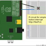
And now the circuit

Circuit for simple button press interrupt
It’s simply a question of rigging up a button connecting 23 to GND when pressed.
And now onto the code
I’ve put most of the explanation in the code, so that if you use it, you will still have it.
#!/usr/bin/env python2.7
# script by Alex Eames https://raspi.tv/
# https://raspi.tv/2013/how-to-use-interrupts-with-python-on-the-raspberry-pi-and-rpi-gpio
import RPi.GPIO as GPIO
GPIO.setmode(GPIO.BCM)

# GPIO 23 set up as input. It is pulled up to stop false signals
GPIO.setup(23, GPIO.IN, pull_up_down=GPIO.PUD_UP)

print "Make sure you have a button connected so that when pressed"
print "it will connect GPIO port 23 (pin 16) to GND (pin 6)\n"
raw_input("Press Enter when ready\n>")

print "Waiting for falling edge on port 23"
# now the program will do nothing until the signal on port 23
# starts to fall towards zero. This is why we used the pullup
# to keep the signal high and prevent a false interrupt

print "During this waiting time, your computer is not"
print "wasting resources by polling for a button press.\n"
print "Press your button when ready to initiate a falling edge interrupt."
try:
    GPIO.wait_for_edge(23, GPIO.FALLING)
    print "\nFalling edge detected. Now your program can continue with"
    print "whatever was waiting for a button press."
except KeyboardInterrupt:
    GPIO.cleanup()       # clean up GPIO on CTRL+C exit
GPIO.cleanup()           # clean up GPIO on normal exit
Decoding the code
lines 4-5 import the RPi.GPIO module and set up the BCM port numbering scheme
line 8 sets GPIO 23 as an input with the pullup resistor set to UP.
This means that the signal will be HIGH all the time until the button is pressed connecting the port to GND, which makes it LOW. This avoids false event detection.
lines 10-11 print some instructions
line 12 waits for user to hit enter before starting. This gives an opportunity to check the wiring
lines 14-21 further instructions and documentation
line 22 try: & line 26 except KeyboardInterrupt:
This allows us to run the program and exit cleanly if someone presses CTRL-C to stop the program. If we didn’t do this, the ports would still be set when we forcefully exit the program.
line 23 sets up the “wait for the signal on port 23 to start falling towards 0”
lines 24-25 further on-screen instructions
line 27 cleans up the GPIO ports we’ve used during this program when CTRL-C is pressed
line 28 cleans up the GPIO ports we’ve used during this program when the program exits normally
Two ways to get the above code on your Pi
If you are in the command line on your Pi, type…
nano interrupt1.py
Then click “copy to clipboard” (above) and paste into the nano window.
CTRL+O

Enter

CTRL+X
Alternatively, you can download this directly to your Pi using…
wget https://raspi.tv/download/interrupt1.py.gz

gunzip interrupt1.py.gz
Then you can run it with…
sudo python interrupt1.py
That’s cool, what next?
So that was a simple “wait for a button press” interrupt. There’s a lot more you can do with them, as I will show you in the next article, which will cover “threaded callback”, which allows us to use the spare capacity we’ve freed up by not polling continually.
Click here for the next article (part 2)
Or check out the official documentation here and press on by yourself.
RasPiO® GPIO Reference Aids
Our sister site RasPiO has three really useful reference products for Raspberry Pi GPIO work...
Interesting… Is there any way to set it up so that you’re waiting to see if either button A _or_ button B was pressed?
Indeed there is Mike. Tune in for another exciting episode where that will be covered soon ;)
Hi Alex,
Greetings.
I was wondering if anyone could point me to where i can find this episode?
Thanks,
RP
I believe you’re looking for
https://raspi.tv/2013/how-to-use-interrupts-with-python-on-the-raspberry-pi-and-rpi-gpio-part-3
Is this Python only?
I hope so otherwise I’ll have to rewrite BerryIO ;)
HeyWhat? Yep RPi.GPIO is Python only. So you C-loving programmers get yer mits off – unless you’re coming over to the
slowenlightened side. :-PPretty sure I’ve seen Gordon Henderson mention something about interrupts in C though at some point.
Here is a working “C” example. This is the JNI code used in the Pi4J project to support interrupts.
https://github.com/Pi4J/pi4j/blob/master/pi4j-native/src/main/native/com_pi4j_wiringpi_GpioInterrupt.c
It was based on Gordon’s examples/suggestions/comments.
Maybe I’m missing something here but that code looks to me like it is using C to poll for pin changes (using a separate thread for each pin) and then it makes a callback to some java thing when it detects a change. i don’t see anything at all to do with receiving hardware interrupts on a level change? (Which is what I’d really like to do. In C.)
You may find one of these links useful?
http://wiringpi.com/
http://abyz.co.uk/rpi/pigpio/
Great to see the latest version of RPi.GPIO now handles interrupts better. I had tried to use interrupts with RPi.GPIO on a project a few months ago but ended up using Python’s epoll API, instead.
I do have a question. I notice the sleep function can’t be interrupted until it times out. Then the interrupt is serviced. Do you know if this is a condition of Python, Raspian or RPi.GPIO? I was thinking sleep could be interrupted running Python under Windows. Not sure now.
Looking forward to the next article on threads.
I will check if sleep can be interrupted with a threaded callback. I rather think it can be, but give me 10 minutes to check it out…
Part 2 will be out on Wednesday. :)
Hee hee. It only took 4 minutes and I was right. It works. You can interrupt time.sleep() using threaded callback. :-D
Excellent! :yes: Probably seemed like a strange question, but sometimes sleep might be part of another completely separate function that is running until interrupted.
Well, you can run another function during the sleep (the callback function runs in a second thread), but I’m not sure if you can actually stop the sleep in the main thread. That will require more than 10 minutes because I’m off to bed. :-)
Depends what you want to achieve. But you could use a
wait_for_edge()instead of a sleep perhaps?Hi Alex
A huge thank you for this article and your work in general..
My old brain is slow to understand all this new stuff but your style of
explaining things suits me fine..
Your efforts are very much appreciated :-))
Philip
You’re welcome Philip. It’s knowing people find it useful that makes it all worthwhile, so thank you for your comment. :)
Part 2 will be out tomorrow and Part 3 on Friday.
[…] Raspberry Pi and RPi.GPIO » RasPi.TV March 19, 2013 By Jack Zimmermann · Leave a CommentHow to use interrupts with Python on the Raspberry Pi and RPi.GPIO » RasPi.TV:We’ve finally got interrupt capability on the Raspberry Pi for GPIO programming in Python […]
[…] How to use interrupts with Python on the Raspberry Pi and RPi.GPIO – part 2 Input and Output, interfacing, python programming, raspberry pi Add comments Mar 202013 Interrupts are an efficient way for a program to be able to respond immediately to a specific event. In the previous article I explained the basics of using interrupts in RPi.GPIO and gave an example of a simple “wait for an event” interrupt program. […]
[…] How to use interrupts with Python on the Raspberry Pi and RPi.GPIO – part 3 Input and Output, interfacing, python programming, raspberry pi Add comments Mar 222013 Multiple threaded callback interrupts in Python […]
[…] How to use interrupts with Python on the Raspberry Pi and RPi.GPIO This is the first in a series of articles which aim to show you how to use this new interrupt facility in Python. […]
[…] RPi.GPIO, now at version 0.5.2a, has interrupts and threaded callback capability. You will probably have seen my three recent posts showing how to use those. […]
[…] It struck me the other day that I’ve published some fairly advanced RPi.GPIO tutorials, (e.g. interrupts and PWM) but not done anything more basic, apart from the Gertboard examples. So here’s an […]
I’m getting the terminology mixed up here and it’s hurting my ability to take this basic tutorial and work it for my project. I have a simple switch that plays an mp3 when I press it. Yeah, works great. Now I’ve replaced the switch with a photo interrupt switch (http://www.seeedstudio.com/depot/photo-interrupter-os25b10-p-541.html) and want the mp3 to play when something passes thru it.
So for this tutorial, the basic switch is open until the user closes it, therefore the voltage to pin 23 is at zero until the user presses and it rises to 3.3+/-, correct?
If I use my photo interrupt, it’s the opposite, light passes thru the sensor so 3.25V is delivered to pin 23 continuously UNTIL an object passes thru the sensor and it drops down to 0.2V. I’ve tried reversing the logic of this tutorial but I’m missing something basic. How would I change this tutorial to detect the voltage dropping when an object blocks the sensor? Thanks! This tutorial has gotten me further along that anything else I’ve found!
No – exactly the wrong way round. The input port is pulled high (3.3V) with the internal pullup, causing 3v3 as the default setting. (That’s what the pullupdown bit in line 8 does.)
When the button is pressed, it connects to ground which makes it go LOW (0V) which is what the interrupt detects. It detects falling voltage.
As it’s written it should work with no changes. But it will only detect one event, unless you put line 23 in a loop (which would probably work quite well in your application).
Hope this helps.
Thanks for the reply! Ok, I understand the tutorial and it makes sense, but I’m confused with the photo interrupt switch, its closed by default, ie 3.3v is being applied to the pin. When the object passes thru the sensor it opens the switch and the voltage drops to about 0.2 (it’s a light sensor so some light is making its way thru). So my switch is opposite of the type of switch you used in the tutorial, and that leads to my question, how to turn the logic in the script around. Would I want to make a pulldown and then watch it fall? My problem is this is my first project like this and I’m probably using the terminology incorrectly! I’m googling like a madman trying to find lots of samples. Thanks!
If you’re waiting for the value to drop from 3.3V to 0.2V, then you’re still waiting for a FALLING edge, and so Alex’s script given on the page above should work fine and not need modifying at all? Which I think is also what Alex was saying?
If we’re still talking at cross-purposes, then maybe you could draw a circuit diagram of exactly what you’ve connected to where?
Here is a picture of the breadboard.
http://i.imgur.com/I1pDkPv.jpg
I’ve got the anode connected to the 5V rail and the Cathode thru a 220 Ohm resistor to ground. On the other side of the sensor I’ve got the Emitter going thru a resistor divider, here a 33K Ohm resistor and then to ground. On the Collector side it’s powered from the 5V rail thru a 22k Ohm resistor and the signal off to pin 23.
When I test this with a voltmeter, I’m showing 3.25V to pin 23 when the sensor is not blocked (sensor’s default state) and about 0.2V when I pass an object between the sensor posts.
Here’s a circuit diagram…hope I got it drawn right! Thanks for responses so far!
Woops, forgot the circuit diagram…
http://i.imgur.com/YzckSYE.jpg
In the picture it looks like the GND pin (#6) is connected to Cathode but the red wire from the 6 pin goes to the ground rail on the left side of the breadboard.
Using red for GND just to confuse us? ;)
Are all your GNDs connected? If your circuit works as you say, the program above should work “as is”, but only once. Can you measure the voltage at GPIO 23 while it’s connected? Maybe we’ve got an issue there?
Here’s a movie. I have one end on the 5v rail going into the colector and the signal going to the pin.
http://www.youtube.com/watch?v=QV-Rd6FW0NI
I’m also a little confused about the difference between BCM and BOARD but since the tutorial here used BCM and showed the switch being hooked up to the same pin (23) I was using, I figured that part has to be right.
The first thing I noticed was that you are measuring between 5V and the GPIO23 pin for your readings.
Shouldn’t you be measuring between GPIO 23 and GND to get a Voltage reading at the pin?
I’m sorry. I don’t really understand your circuit.
Alex, that’s awesome, I don’t even know what I’m measuring! This is my first project like this. Obviously I’ve got something backwards. Measuring it as you mentioned shows 1.6V at pin 23 and 4.0V when I block the sensor. I’m guessing my resistor divider is doing a little too much dividing!
You don’t really want to be sending 4.0V down a pin designed for 3.3V I’m not sure what the tolerances are, but that’s either getting a bit close to damaging the port, or it might already be there.
Voltages are always measured against GND, generally wiring is done so that positive is red and GND is black.
I knew not to send more than 3.3, the way I was reading it it looked fine but obviously that is not the case. Any suggestions on how to get 5V down to 3.3 in the diagram I made? I was using the 22K and 33K resistors, I’ll try switching them around to see what happens. I got that from another thread on how to step 5 down to 3.3. Thanks for the help so far.
This reply may be a bit late but I’ve only just discovered this website. If you still need a solution then first you need to rewire your opto sensor.
Having looked at your circuit diagram, what you need to do is connect the emitter directly to ground, not through R3. Then remove R2 (so neither resistor is needed, R3 needs to be a link). Leave the collector connected to the Pi input. That input already has an internal pull up resistor and the opto transistor will pull it down when the slot is clear.
With no object in the opto sensor slot the input to pin 23 will be low. When an object is in the slot the input to pin 23 will be high, so you are right in thinking than the logic is reversed and the code will need changing to reflect that. I am new to Pi so can’t help with the code but it must be quit simple to some people on here.
Hope this helps!
Great articles … but I’m having difficulty with the GPIO module.
It imports OK , but GPIO.VERSION throws an error
Here’s a result of using the find command
sudo find / -name ‘*RPi*’ -print
/usr/lib/pyshared/python2.6/RPi
/usr/lib/pyshared/python2.7/RPi
/usr/lib/python2.6/dist-packages/RPi
/usr/lib/python2.6/dist-packages/RPi.GPIO-0.5.3a.egg-info
/usr/lib/python2.7/dist-packages/RPi
/usr/lib/python2.7/dist-packages/RPi.GPIO-0.5.3a.egg-info
/usr/local/lib/python2.7/dist-packages/RPi.GPIO-0.3.1a-py2.7-linux-armv6l.egg
/usr/local/lib/python2.7/dist-packages/RPi.GPIO-0.3.1a-py2.7-linux-armv6l.egg/RPi
It looks like /usr/local might have version 0.3.1 ?
Any suggestions as to how to proceed?
jim
You’ve got an older version that may have been manually installed? Not sure how to get rid of that, but hopefully someone’ll be along in a minute who can help you. (You could reflash the card, but that’s a bit drastic – and there IS a way – I just don’t know it.)
It’s not something I’ve done myself, but there’s a whole bunch of useful-looking answers in Google ;-)
http://www.google.com/search?q=undo%20python%20setup.py
Alex, great write-up, helped me out some.
just a question, what if I want the button to do more than just print something on-screen?
I tried this code:
def my_callback(channel):
device.emit(uinput.KEY_N, 1) # PRESS N-KEY
print “falling edge detected on 17”
def my_callback2(channel):
device.emit(uinput.KEY_P, 1) # PRESS P-KEY
print “falling edge detected on 23”
and it kinda works, once. If I press the button it will do the ‘n’ on screen once, every other time I press the button it only prints out the text in terminal but not the ‘n’.
Sorry, put it in the wrong place, should be in part 2 of the series, still the question remains open, I cannot get it to work.
everytime I press the button it prints “falling edge detected on 17″ in the terminal and the first time it also prints “n” on the screen, but
that is only the first time, the second time no more “n” on screen.
Well if the text is being printed multiple times then “device.emit(uinput.KEY_N, 1)” is definitely being called multiple times, so the problem must be with with your “device.emit” function (whatever that might be) being called multiple times, rather than with the GPIO interrupt handling.
If you could post the full source code (rather than just a snippet) that might give us a better idea of what is going on :)
Here is the full code:
#!/usr/bin/env python2.7
import RPi.GPIO as GPIO
import uinput
import pygame, sys, os, time
from time import sleep
GPIO.setmode(GPIO.BCM)
device = uinput.Device([uinput.KEY_N])
GPIO.setup(17, GPIO.IN, pull_up_down=GPIO.PUD_UP)
def my_callback1(channel):
device.emit(uinput.KEY_N, 1) # PRESS N-KEY
print “falling edge detected on 17”
GPIO.add_event_detect(17, GPIO.FALLING, callback=my_callback1, bouncetime=300)
while True:
print ‘Waiting for input.’
sleep(60);
Nothing fancy, just waiting for a button to be pushed, and it should act as if the letter ‘N’ was pushed on a keyboard.
prints ‘n’ once on the screen, and then just “falling edge detected on 17” in terminal on every other push of the button.
Hi,
I just wanted to know anyhow I can calculate the frequency of the signal which I am getting from the sensor that is connected to raspberry pi? Please help me on this. Thanks
I guess one way to do it would be to set up an interrupt on a falling edge, and then set up a threaded callback function (see Alex’s other article) which does something like:
def my_callback(channel):
    if do_measure:
        global counts
        counts += 1
and then in your main code (after setting up the callback etc.) you’d do something like:
Note however that this probably won’t be very accurate, and it’ll only allow you to measure fairly low frequencies. I haven’t tried this myself so you’ll have to experiment to see how reliable it is!
ARDUINO INTERUPT TO RASPBERRY PI
hey Friends :)
just thought that could be interesting for you.
I was searching for a way to get an interrupt to the raspi when a touch sensitive button on my arduino was touched.
the arduino handles some leds when the button is touched and the raspi should display it.
further you can control the leds on the arduino from the raspi gui. the raspi sends the data how to set the leds with i2c.
because the i2c only works from master to slave i have to send the raspi an interupt to fetch the new data from the arduino by sending a request.
this is not the full code – just an example:
here is the raspi python code:
#!/usr/bin/env python2.7
# script by Alex Eames https://raspi.tv/
# https://raspi.tv/2013/how-to-use-interrupts-with-python-on-the-raspberry-pi-and-rpi-gpio
import RPi.GPIO as GPIO

def send_1c2_req():
        print "send the request to arduino"

while True:
        GPIO.setmode(GPIO.BCM)

        # GPIO 23 set up as input. It is pulled down to receive the signal form arduino
        GPIO.setup(23, GPIO.IN, pull_up_down=GPIO.PUD_DOWN)

        print "Waiting for falling edge on port 23"

        # raspi is now not looking for falling but rising edge. so if the digital pin on arduino goes high it triggers the raspi
        try:
            GPIO.wait_for_edge(23, GPIO.RISING)
            print "\nRising edge detected."
            send_i2c_req
        except:
            print "something happend..."
            GPIO.cleanup()       # clean up GPIO on CTRL+C exit
        GPIO.cleanup()           # clean up GPIO on normal exit
here is the arduino code – it just switches states all 1 sec – the interrupt will appear all 2 sec:
#define INTERRUPT 12 #define CONTROL 13 void setup(){ pinMode(INTERRUPT,OUTPUT); pinMode(CONTROL,OUTPUT); } void loop(){ digitalWrite(INTERRUPT,HIGH); digitalWrite(CONTROL,HIGH); delay(1000); digitalWrite(INTERRUPT,LOW); digitalWrite(CONTROL,LOW); delay(1000); }I downloaded the code, unzipped it and started the code. The program starts as expected (I see the message “make sure you have…”) but the program doesn’t react to pressing the button, I checked with a voltmeter whether the voltage on bmc-pin 23 is dropping from 3.3V to zero when I press the button and it does. I’m using GPIO-version 0.5.4 Can anyone here help me further?
thanks
jean
Jean. I’d put money on you having wired your button to P1 header pin 23 instead of GPIO23, which is pin 16
Dear Alex,
I did use gpio23 just exactly as is shown in the schematic and I am also able to read the state of a switch connected to that pin but it doesn’t work in interrupt mode. Any further ideas about what could cause this?
thanks
jean
Maybe you’ve not got the right version of RPi.GPIO installed? (or you might have conflicting versions installed)
https://raspi.tv/2013/rpi-gpio-basics-1-how-to-check-what-rpi-gpio-version-you-have
May I ask why exactly did we choose pin 23 ?
We could have used any GPIO port, but GPIO 23 (not pin 23) was chosen because it has a GND next to it, which makes it convenient for wiring.
(Pin 23 is GPIO 11/SCLK)
Thanks alot for your quick response and this tutorial has really helped me.
Not yet even a bad programmer in Python yet, as most of my work has been in the B&D languages (well, people are still using Fortran and Cobol,) and I have no intuition about Python’s functioning yet — nor the hardware side of the Pi.
I would appreciate a quick “off the cuff” response as to feasibility of an interrupt being inherited by a spawned child program.
I am writing software for a research project that would video individuals with a sleep disorder. This would use the existing Linux version of the GPL software “motion” and “raspivid.” There would of course be times when the patient might want to have some privacy for a short time, so it would be highly desirable to be able to kill or suspend (preferred) all monitoring for a few minutes, and then again resume via a second interupt.
I would be grateful to know if this is a reasonable approach, or would not possibly work on the Pi.
Thank you for your consideration.
Sounds like you’re confusing your “interrupt”s ;-)
It sounds like you’re talking more about https://en.wikipedia.org/wiki/Unix_signal for inter-process-communication than about triggering functions asynchronously from within Python.
Although of course there’s no reason you can’t combine the two: https://docs.python.org/2/library/signal.html
Hi! I have a little problem here I hope you can help me.
I need to interrupt the main thread of my program but I don’t want to run a new thread. I just want to when I press a button cause an interruption of the main thread.
I have read this post but neither of the options that mention here works for me.
I’ve also read something about using wiringpi2 library, precisely the function wiringPiISR. But every time I execute my code, no matter if the button is pressed or not, the function callback executes anyway.
Thank you very much
I’m not familiar with WiringPiISR
But the interrupts described on this page use RPi.GPIO
I believe it is possible to use both systems in the same Python script as long as you don’t try to use the same ports for each.
It does look, in your code, as if you have set up WP pin 2 as an input, then tried to write a value to it as if it was an output. Can you even do that?
Yes, actually I was trying to fix that error that I metioned before. The original code was:
wiringpi2.GPIO(wiringpi2.GPIO.WPI_MODE_PINS)
wiringpi2.pullUpDnControl(2,1)
wiringpi2.wiringPiISR(2, 0, my_callback())
Anyway, using RPi.GPIO there’s no way to interrupt the main thread? I mean interrupts but not running a new thread.
Thank you very much for your answer, it’s a very good page.
Depends what you mean by “interrupt” ? I guess you could do something like:
import RPi.GPIO as GPIO
import time

keep_running = True
seconds = 0

def my_callback(channel):
    global keep_running
    print 'Button pressed'
    keep_running = False

GPIO.setmode(GPIO.BCM)
GPIO.setup(23, GPIO.IN, pull_up_down=GPIO.PUD_UP)
GPIO.add_event_detect(23, GPIO.FALLING, callback=my_callback)

while keep_running:
    # insert your main-loop code here
    print 'Running for %d seconds' % seconds
    time.sleep(5)
    seconds += 5

# if we get to here we have been interrupted
print 'Program interrupted'

GPIO.cleanup()
(note that this is off the top-of-my-head, and totally untested)
Obviously this will only be “interruptible” at the start of each loop, and not within the call to sleep().
Is there any way to use Nrf24l01+ with interrupt on Rpi? I was using a C script to read all data that arrives by the module. But the script consumed 99.9% CPU.
But now I’m using a arduino connected at serial and all data arriving from arduino + nrf is written by serial and the ruby script read it. But again, the ruby script consumes almost 99.9% CPU.
What is the better way for read the informations from nrf? Thanks.
Great tutorial and great code. I used this tutorial to connect my front doorbell to a Raspberry Pi. I altered the code in the example so that if someone pushes the doorbell an API (from Pushover) is activated which send a pushnotification to my iOS device. I added a loop so when the doorbell is activated once, the GPIO pin is pulled up again ready for the next event. Initially the code works great, but I ran in some problems:
1.) For some reason events are occurring on 20-30 minutes interval without pushing any button. Is this a false event?
2.) The program closes when I quit the SSH session with the Raspberry Pi.
Any idea to solve this?
1) are you using hardware pullup resistor? If it’s random radio interference that should cure it. Also ensure you have the latest RPi.GPIO as there were some bugs in the interrupts part of some earlier releases.
2) unless you run it in the background, or via soeothing like ‘screen’ https://raspi.tv/2012/using-screen-with-raspberry-pi-to-avoid-leaving-ssh-sessions-open closing an ssh session will terminate whatever program you started with that session
A better option for 2) would be using http://www.raspberrypi.org/documentation/linux/usage/rc-local.md
Thanks, I definitely give it a try once I solved 1.)
1.) I added a pull-up resistor to the circuit consisting of a 10k resistor connected to the 3,3v pin according: https://learn.sparkfun.com/tutorials/pull-up-resistors. At the moment I’m testing the new set-up.
2.) Great tip
[…] the script there is a link to https://raspi.tv/2013/how-to-use-interrupts-with-python-on-the-raspberry-pi-and-rpi-gpio. It is a great resource for GPIO for the pi. I used it to research the glob error I was getting […]
Great post! Just curious how you would use interrupts with a slide switch?
You mean like a potentiometer slider?
I imagine somewhere in the middle it would flip from 0 to 1, but no idea at what threshold.
I wouldn’t really have thought it was the right tool for the job, to be honest.
No blatant plug for the ADC features of RaspIO Duino, Alex? ;-)
OTOH if Mark meant an on/off slide switch like http://www.maplin.co.uk/p/single-pole-sub-miniature-ff77j then you’d use it exactly like a push button in Alex’s example above (you only need to connect two of the switch’s three pins, but remember to use the Pi’s internal pull-ups).
You know what Andrew? I must be tired after the Pi birthday weekend because I didn’t even think of it :)
Yes, just like that on/off slide switch. I’ve set it up on pin 22 and ground. Is there a way to intelligently determine if the switch is on or off? With my code below, every time the event fires, it prints “Switch was switched”. Of course I could keep track in a variable but just curious if interrupts and events could do this some how?
Also, how do you handle bounce with a slide switch? The old way of doing this in a loop and checking every xx milliseconds was able to catch the on/off position of the switch if you move it back and forth as fast as you can. Doing it with the above code often misses 1 or 2 on/off slides unless you slow down how often you are switching it. Any suggestions? Here is the old way I did this:
This is exactly what I need Thanks! Although I’m having some trouble executing a response to the button press. As soon as I press the button I want the Raspberry Pi to run a command as if I had typed it in the prompt. From my brief research I understand that subprocesses are the way to do this, but anyway I enter the subprocess in the response portion of the code in your tutorial, I get this error:
subprocess.call(‘ls’,shell=True)
^
SyntaxError: invalid syntax
When I run that same subprocess in it’s own python code it runs just fine, but it doesn’t like it in this program you’ve written :/ Any idea why? I would greatly appreciate any help on this Thanks!
Did you remember to include the subprocess module with a line like:
import subprocess
?
And don’t forget that indentation (number of spaces) is important when writing Python code. Also, “just to be on the safe side” you’re probably better off giving the full path to the command, i.e. use ‘/bin/ls’ instead of just ‘ls’.
This is a very helpful series. I just got my RPi 2 today and everything is going nicely, except…
On this setup, the button works just fine, but Ctl-C gives me a runtime error: “Error waiting for edge; During handling of the above exception, another exception occurred, KeyboardInterrupt.” I’ve tried the obvious, like adding a “finally” clause, and an “except RuntimeError” clause. My version of Rpi.GPIO is 0.5.11.
Hi, Nice Tutorial. But when I tried to implement it on my RPi rev 2 with Jessie OS. I don’t get any interrupt when i connected one of my GPIO to the GND and detecting the falling edge. I am working on the following code.
    import RPi.GPIO as GPIO

    GPIO.setup(38, GPIO.IN, pull_up_down=GPIO.PUD_UP)

    try:
        print "Waiting for falling edge"
        GPIO.wait_for_edge(38, GPIO.FALLING)
        print "Falling edge detected."
    except Exception:
        print 'No GPIO present'
        GPIO.cleanup()
    GPIO.cleanup()
Can you tell me where did I do wrong? I have also updated my OS recently, but still it is not responding. What should I do?
You’ve omitted to set the GPIO mode (line 5 in my code)
GPIO.setmode(GPIO.BCM)orGPIO.setmode(GPIO.BOARD)since it looks like you’re using pin numbers not GPIO numbersI copied the code in this article and had a wire of 25 cm connected to the pin of GPIO23 not connected to anything. After that I immediately get the falling edge message. When I remove the wire the timeout kicks in. It looks like the pull up, although setup, is not working properly.
Erm, huh? If you’ve got a wire connected to a GPIO pin with the other end not connected to anything, what are you expecting it to do??
Because of the pull up I expect no interrupt. I found information mentioning this effect. Without the pull up the input is floating making it susceptible to these stray signals, but the pull up prevents this. Apparently not.
Ahhh, the Pi only has weak internal pull-ups, so if you’ve got an open-ended (relatively long) wire then it indeed may be acting as an antenna as Jim mentioned, and getting enough interference to override the weak pullup and trigger the interrupt. As you’ve already found, the fix is to add an external resistor to give a “stronger pull”.
Perhaps the wire is acting like an antenna and stray electrical signals are triggering the interrupt. What happens if you connect the wire to ground through a high-value resistor.
I used a 47k ohm resistor to ground and I did not get a falling edge till I made shortcut over the resistor.
The example mentions a switch on a breadboard. Does such a switch have a high value resistor over its contacts or is a complete open switch? I wonder what is in that case the difference with my open wire?
On this occasion I used no resistor.
Hi Great Tutorial, I have used it to set-up a four button system to control my LCD screen on a remote weather station (to save power as solar and switch screen on/off as needed), I would like to remove or amend the Raw Input so that I could use it to auto run at the Pi startup, have tried removing the Raw Input and it runs but stops after a time, I presume by a timeout.
is there something I can use to overcome using Raw Input as the system tests well except for the need of the Raw Input stops the use of auto startup.
any ideas please.
What do you mean by Raw Input. I have a Python script which is started with a @reboot in a crontab entry. It contains an endless loop and a routine executed on a falling edge on one of the pins. It is already active for several weeks.
Another option is to define the program as a one shot service in systemd. You may use the example of the fake-hwclock package to define the .service file.
Perhaps you’re looking for something like this? http://gpiozero.readthedocs.io/en/v1.2.0/notes.html#keep-your-script-running
I finally found the problem. I use openSUSE Tumbleweed for Raspberry Pi, which does not have a /sys/class/gpio/gpiochip0 device, but a /sys/class/gpio/gpiochip298 device. I adapted the RPi.GPIO package first in the wrong way; the package assumes the zero in the device name. Some functions were OK, but not the setting of the pull up. My latest adaption works OK.
I love you man. I like it that you keep it clear and simple
Something interesting happened.
I was reading this article at my coffee table, so I just connected tow wires to GPIO pin 23 and a ground pin. I just connected these two wires to emulate the switch. Everything worked fine until I did not disconnect the wires. The wires were connected and emulating a pressed switch when I started the program. After pressing the program immediately reported a falling edge and terminated. But there was no falling edge, just LOW condition. The program I used was copied from your text.
So what is wrong here?
Thank you for bringing me to the new idea of executing codes on RPI….
I need to trigger a RPI camera and execute a code on RPI when the door is opened…. Does your post work for me?