Don’t try this unless you know what you are doing. Mains electricity can kill you.
Update
Since publishing this blog post, I’ve had some feedback about the way I’ve done this and it needs improvements and a redesign to make it safer. Please don’t copy this. I’ve removed some photos so I’m not setting a bad example.
Back to the original post
Ever since getting my Gertboard in late September, I’ve been thinking about using a Raspberry Pi to switch “proper things”. By “proper things” I mean real, useful, BIG things using mains electricity. :eek:
The Gertboard has a relay controller, but to actually switch anything larger than a few millivolts you need to attach relay(s).
What’s a relay?
A relay is a device which allows a low power circuit to switch a higher power circuit. In the most popular relays, the switch is controlled by an electromagnet switch (solenoid). When there’s current flowing through the low power circuit, an electromagnetic solenoid switch flips from one position to another, switching on/off the higher power circuit (depending on how it’s set up). It makes an unmistakeably characteristic “click” sound. relay-click Click the play button to hear the relay click sound.

5V relay
Learning from the Gertboard
So I bought some relays to experiment with. The first thing I noticed was that the feet of the relays don’t line up very nicely with a standard breadboard. So they had to be bent a bit to make connections. I can see people breaking these with frequent plugging in and out of breadboards. :(
I did some preliminary tests with the Python version of the Gertboard ocol (open collector) program I wrote, using it to switch leds on and off. I love leds, but they’re a bit tame aren’t they? ;) I want to switch some “proper things”. That means connecting up to mains electricity. :eek:
The other thing the Gertboard taught me was how to use a Darlington Array. Without going into great detail (because I don’t know it :rotfl:) a Darlington array is a collection of Darlington Pairs. A Darlington Pair is a pair of transistors used for amplifying a very low switching current up to a useful level.
The Darlington Array on the Gertboard has 8 Darlington Pairs on it, but 2 are not connected (which is why it can run 6 relays, not 8). I got hold of some cheap Darlington Array chips and decided to do some experiments directly interfacing to the Pi. But first there was some hardware work to do.
Mains electricity + breadboard = bad idea
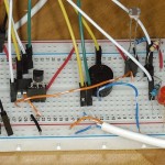
There’s no way you’d get me (or anyone sensible) plugging mains-connected wires into a breadboard. Too hazardous. :eek: No. What was needed was proper screw terminals and the relay soldered down onto a proper board. A PCB (printed circuit board) with holes in the right place for relays and screw terminals for the mains wires would be a good solution, but I made do with stripboard for the time being.
So I decided to solder up a 5 Volt relay, Darlington Array and screw terminals onto a piece of stripboard. I still had to bend the legs on the relay a bit, but, once soldered down, they’re there for good. You’ve already seen the top side of the board.
Test positive
A quick test with a mains powered lamp, with a hacked plug, provided proof of concept. A click, not a bang!
YAY – it works just like it should. :yes:
Then, much piddling about in a live Python environment ensued; enjoying the simple satisfaction of being able to switch a lamp on and off at the touch of a keyboard.
This opens up all sorts of possibilities
Then my mind started wandering…
If you can use your Pi to switch on a lamp…
…and your Pi is connected to the internet…
…and you have a smartphone…
…you can log into your Pi and switch it on/off with that 8-)
The possibilities for remote and/or automated control of virtually anything just became a reality. The possibilities are limited only by our imagination (and maybe our budget ;)).
OK, but I need a demo for the next Milton Keynes Jam
So my daydream about remotely controlling the universe by connecting relays to my RasPi met with the harsh reality that the MK Jammers would be expecting me to come up with something…
- new
- avant-garde
- eye-catching
- and hopefully just plain fun.
Last time we had flag waving, but, although that’s extremely cool, that is soooooooo September. The world’s moved on. We need something more. ;)
- We need a RasPi-switched, mains-powered fan, run by a Python script and temperature sensor. But that’s not enough…
- We also need a RasPi-switched, mains-powered lamp, running from the same script, with a light sensor to tell it when it’s dark enough to switch on. But that’s still not enough…
- We need a beeper to alert us when the fan is going to spin up (I’ve got no guard on it – hate those things). More…
- We need different beeps for fan and lamp. More…
- We need an indicator led, pulsed with the beeper. More…
Ain’t you getting a bit greedy? ;)
OK, let’s have some custom sounds as well (even if it’s only recordings of me talking). Just so we can have it super silly, fun, eye-catching, attention-grabbing, noisy, interactive, memorable…
And it’s all got to be safely packaged. So here’s what we ended up with…
Sweet, stuff like is what i have been having in mind as well.
Great explanations!
Thank you :) This just unlocks a whole new world of awesome possibilities.
Neat! Connect this up to your home thermostat control line for your boiler and you have a very sophisticated temperature control for the house. Multiple temperature readings can be used, along with remote control over the web. Now that is a really useful idea. Know of anyone who has done this?
Oddly enough, I do. There’s a chap called Daniel Bull who goes to the Milton Keynes Raspberry Jam. He’s also the one who wrote BerryIO…
https://raspi.tv/2012/berryio-a-browser-based-io-control-system-for-raspberry-pi
…his heating controller broke a couple of months ago and he’s made one out of a Pi because it was…
a) cheaper
b) a heck of a lot better with display of weather forecasts pulled from the internet and target temperatures
If you or Daniel have any details of what youve done Id love to see them.
Cheers C
There’s a thread about Daniel’s heating controller on the MK Jam forum. I don’t know if it’s publicly viewable though. Try it and see :)
http://www.peteronion.org.uk/smf/index.php?topic=27.0
Thanks a lot Alex it is publicly available. Working way through it now.
C
[…] upravljanje pri vklopu in izklopu stvari. To je zares odličen vodič, lahko pa si ga preberete na Alexovem blogu, del pa si ga ogledate v spodnjem […]
Nice work Alex.
I have bookmarked your web site.
Your detailed explanation is great.
I learned a lot from your presentation.
Thanks.
Thank you :)
Hi,
Just a quick comment, it looks like the relay switch common pin is really close to the ULN2003 ic, close to an unsoldered pin.
Basically the strip 5 rows from the bottom on the last diagram, you can see the soldered common pin close to the orange wire. If you follow that row 5 to the right, it goes around an unsoldered ULN2003 pin.
The quick way of fixing this is to remove a lot of the unused copper strips with a knife. Really the distance should be a lot (>10mm from memory).
It is cut under the orange wire, but thanks for the tip. I will make a larger gap :) I’ve now dremelled out a lot of copper – see new photo. :)
Great, looks much better. Also, as a suggestion, it is worth investigating optocouplers, or a ‘Solid State Relay’ which contains it built-in. There are a couple of types, depending on if your load is going to be inductive or not. Also, for conventional relays, for the few times that I have needed to, if there is no PCB, then there is also ‘plug-in’ relays that go into a base socket that has screw connectors. This allows you to wire directly to the relay socket without using any stripboard. If you want to strap the wires, relay and socket down, you can use a plain board with no copper on it. But I agree with Michael below, the regulations will have it all explained far better.
This project is insanely dangerous. UK mains voltages can and do kill people. Mains should NEVER appear on stripboard. There are sensible regulations which specify levels of insulation and creapage clearances as well as test methods to ensure that mains powered equipment is safe.
The current MagPi has an article about a safe way of controling mains powered equipment from the Pi (using low cost radio control stuff).
MK
Thank you for your concern Michael. I’ve looked up the sensible regulations, so am taking steps to ensure compliance. :)
I hate to sound so negative Alex, but if you think that just having 5mm clearances (as you mentioned in your email) is enough then you are way short of the mark.
As a starter can I recomend that you look at http://www.penguintutor.com/electronics/electrical-safety
If you are going to apply mains voltages to DIY stuff you need to be extra careful – when you are publishing an article which other people might follow much more careful again.
For DIY stuff mains should never be on the same board as the safe low voltage stuff. The isolating device should be a transfomer or solid sate switch or relay specifically approved for the purpose.
MK
The site sent you an email, I didn’t. I amended the comment as I wanted to do further research to check it was accurate.
I’ll be totally honest, your first comment was really upsetting. And the hyperbole made it harder to take seriously. I think I’ve proved I’m not insane by taking action based upon it (and by allowing it to pass through moderation).
You are of course right that mains voltage needs to be handled with great care and there is a responsiblity to publish wisely.
Thanks for the information. I don’t consider myself above criticism and am keen to learn how to do things properly. :)
Hello Alex,
The automatic email sent by the site was different from the actual posting so I didn’t realise that it was automatically sent at first – sorry.
I’m also sorry if I offended you but this whole mains thing really does matter. The data is not made available very quickly so the latest year we have UK figures for is 2007 when 28 people died directly from electrical shock (19 at home, 9 at work) (http://www.esc.org.uk/industry/policies-and-research/statistics/). The number seriously injured either by shock or electrically started fires is much higher.
One of my big gripes is that the EU and the UK Gov. make rules but expect you to buy the standards that they call up – I had a quick look and I couldn’t find anything free that would help you with detailed design. I spotted quite a few books (eg Practical Guide to Low Voltage Directive By Gregg Kervill which looks quite good) but they are expensive. You might be able to get your local library (if not closed down) to get it for you.
MK
I do have to agree with Mr Kellett here. 240v IS extremely dangerous and needs to be handled VERY carefully.
At the very least the relays should be segregated from the circuit, either by mounting the relays in another box or using a bigger box with a division, they should be mounted on a proper relay base (if a PCB designed for the job isn’t used), one with screw terminals designed to carry 240v. You cannot have 240v in such close proximity to extra low voltage circuits & cables. The wires supplying the 5v to the relays (in the segregated area) must be mains rated and not telephone wire.
Another thing I noticed was the earth cable coming from the lamp holder, it doesn’t go anywhere!!!! If something requires an earth it MUST be connected back to earth.
Just one other note, the relays are rated at 10A, that 10 amps depends on the type of load you have. A resistive load such as a lamp or electric fire is fine but if you connected an inductive load such as a motor or a transformer. That 10 amp rating suddenly becomes 2-3 amps at best. It’s probably fine with a desk fan but if it were a washing machine it would burn out and possibly catch fire.
Here’s a brief explanation of segregation.
http://www.tlc-direct.co.uk/Book/6.6.1.htm
http://www.tlc-direct.co.uk/Book/1.1.htm
It’s a little outdated as it refers to the 16th Ed IEE regs while we are currently on the 17th Edition, but any info is better than no info.
Sorry if I sound blunt but it’s people’s lives you have to think about. If it were a gas line and you wanted to control a gas fire with a solenoid valve would you do it? I wouldn’t.
I know this project was done with the best intentions but please put safety first.
Stu
Thank you that’s really helpful :) I’m going to change the setup to use an opto-isolated PCB and segregate it from the mains wires.
I think I’m going to pull some of the photos so that people won’t be tempted to copy. :(
I’m liking the look of this… I want to do much the same thing, with the specific purpose of building a computer controlled fermentation controller with a web interface for controlling homebrew beer fermentations. There are a lot of controllers out there that are solid state, some PID controllers that do cool stuff, a very few temperature loggers that can be used with a PC, but nothing that does all of that. Raspberry Pi might be a good platform for this.
I think the Pi can handle all of that. Be very careful with mains high voltage though. See Mike’s and S’s comments above. :)
Check this out http://brewpi.com/
Yep its a brew platform controlled by Pi.
Cogs
Alex,
If you would like to email me directly I can help you design a totally safe way to switch mains by Pi based on cheap radio controlled mains sockets from Amazon – this will avoid all the problems raised with relays.
Thanks Michael :) I may well take you up on that. I’m going to have a read of the MagPi article first.
(Removed your email address for privacy.)
OK so lets just accept that people are going to do this sort of thing so lets help them not kill themselves.
Take a look at this http://arduino-direct.com/sunshop/index.php?l=product_detail&p=359 . If you care to read this http://arduino-info.wikispaces.com/ArduinoPower#ACDC then you can read up about some of the issues to do with switching power.
Comments, is this component safe? How would you know?
Alex, I would recommend that you put some kind of disclaimer on your video or something else you might get sued by the idiots who dont know better.
C
I’ll put one on the Youtube page. There’s already one on this page now. (edit – I’ve put one on the video too).
@Cogarooni,
The two items you link to say nothing about safe mains wiring or use. The little Arduino relay board may or may not be safe in itself (I have no way of telling from the picture) but if it isn’t wired up correctly (which includes earthing, enclosure, clearances, fusing, rcd etc then using it can still be dangerous). Since it is possible to switch mains by buying cheap RC controlled sockets (re. the MagPi article) I feel it is much better to encourage the inexperienced to go that way.
Michael Kellett
Michael
Im kind of surprised by your post Michael, other than re-iterating it might be dangerous, (no offence meant this a common saying in the US) but no shit sherlock, this doesnt help people. I would have expected you to say, well it should have CE marks on it, or the specification of the board appears to be safe, or there is no specification of the board, or the website makes no mention of basic safety methods to be used to make sure it is safe when used in a particular way, or here is a simple set of instructions about best practice. Or if you really want to do this safely then you should go take a course in electrical safety.
BTW, I have looked at electrical installations done in both industrial environments and domestic environments and on the whole they are very good, however Ive also seen work done by people who allegedly have the right technical qualifications who frankly should go on a very serious refresher course before they either cause a fire, kill themselves or kill others.
Im curious to know what your technical qualifications are? Perhaps you are unable to say what should be safe or point people in the right direction. Yes I’ve read the article about using RF and while it might fit some applications it wont fit all. If you cant help and you are concerned individual thats OK too, but saying no dont do it doesnt work! Good example is drugs for example, people know it may/will kill them but they still do it!
Well done Alex on the update. Maybe an article on safe use of these kind of devices should go into the Magpi, any volunteers to help write it.
Just to re-enforce my point http://www.raspberrypi.org/archives/2688
C
@Cogarooni,
No offence intended here either but if you are in America this may explain why you don’t share my concerns re. use of mains electrcity. In the US domestic mains is a much safer 110 V rather than the 230 we use here in the UK. The difference is that you can expect to get away with a mains shock without injury in the US and you may well not in the UK.
Safe use of mains electricity is a matter of training and experience – it can’t be imparted to the world in a few well chosen notes on a web site.
I don’t usually design mains powered equipment in my professional work which is why I don’t presume to tell anyone else how to do it – I’m just trying to make sure that people are aware of the risks.
Michael Kellett
You couldn’t possibly know this Michael, but Cogarooni has a UK email address, which he uses to log in on the site, so I think he’s over here – just borrowed a phrase from across the pond. :)
Tks Alex, yes I am UK based. Michael I think you may have got the wrong end of the stick from my postings, not to worry its easily done. No offence taken either.
I completely agree that unless you know what you are doing then you most certainly shouldnt be messing around with anything electrical.
Actually voltage doesnt kill you its the voltage/current (ie power) that kills you, thats how something like a Van De Graff generator which generates millions of Volts is used for things like hair raising experiments but doesnt actually kill you, the voltage is massive but the current is well miniscule. DC voltage of say 48V can also kill you if there is enough ummpph behind it. Of course this is a bit of a simplification and voltage, type AC/DC/frequency all have an impact. Thats how RCD breakers work, if you are exposed to, say 240V, they detect the current imbalance, ie leakage through you to ground (or if there is a fault) and break the circuit very quickly before the current kills you! Not meant as a lecture just a bit of a debate to help establish a bit of credibility.
Good advice would be use an rcd on the mains supply as a minimum but dont rely on it.
FYI I have a degree in electrical engineering (long time ago) but I havent done any wiring in decades as Ive been working on large system wide things and nothing whatsoever to do with power engineering which never was a favourite of mine – far too dangerous! Hope you dont take this the wrong way, Im not bragging just stating the facts. I just want to let you know I am not an irresponsible idiot and do have more than a laymans understanding of the topic.
BTW I also think you have done a good thing by opening up this issue, as I did look at Alex’s pictures and thought that doesnt look too safe, however you took the initiative so are to be congratulated.
I am of course aware that the IET Wiring Regs are the UK definitive bible on these sorts of things but unfortunately havent read them and they arent available freely online sadly. Maybe a visit to the IET library is in order here. Of course CE marks play a role in this, again a massive topic and not something I am qualified in. I noted the arduino board didnt have any CE marks on them, but dont know enough about US standards to see if they had been tested there. Of course, legally you should not modify your electrical equipment connected to mains in the UK unless it is tested and approved by a qualified electrical technician, and you have the certificate for the work, an EIC I believe it is called, not sure if that applies to appliances or stuff like this – perhaps you know.
Anyway, as I said before, its one thing warning people, its another thing stopping them! Hence my pragmatic approach of attempting to get some sensible advice in place for people, it should not exclude a suitable warning about the dangers involved. You may take the alternate and perfectly valid view that says providing any information is dangerous and only warnings should be provided. If so lets agree to disagree.
Alex, happy to help out in anyway with this to the best of my abilities.
Best wishes, merry xmas and a happy and safe new year to you both.
Alex, Id missed / not fully read the comment by Stu An Electrician or followed up on his links.
Good post Stu, very constructive.
Stu’s advice looks pretty good to me, ie:
– warning labels so that no one messes about with your stuff accidently
– proper physical isolation/separation of low voltage and high voltage
– use of cables/components in individual areas (of voltage classification) rated for the highest voltage, ie as he says power cable connecting a completely separate area of control electronics to the power switching parts
– complete physical separation of control electronics from power electronics
– proper earthing throughout the whole system, particularly to any metal cases (ideally everything should be plastic ie non-conducting and suitable robust for the intended use
– Stu do you think an rcd should be used for the power supply that is being controlled.
Alex hope thats constructive, of course you should re-iterate the message about mains being dangerous.
Cogs
Yes it was a good post. :) Thank you for your input too Cogarooni :)
Hi Cogs
If your house has fairly ‘up to date’ wiring then it should already have RCD protection in the fuse board (you can usually tell by the test button on at least two ‘fuses’). But if in doubt use an rcd protected extension.
The link from a post later on/further down (http://www.powerswitchtail.com/Pages/PSTKKit.aspx) appears to looks OK, but please be aware the cable grips don’t look up to much and continuous movement/sudden jerk could damage/break the supply connections.
Also the 20amp rating is for the relay only, that will be a resistive load not inductive (so probably not a good choice for your washing machine). As I mentioned in my original post an inductive load (motors, transformers etc) seriously reduces a relay’s power rating (and it’s a lot lower than the max 13A rating of a UK socket). It might be worth asking them about the actual rating for the whole board, resistive and inductive.
I do plan to do a similar thing but the problem with wiring a switch directly is you need a PI for each switch, you can’t practically run control wires around your house. I will be looking into either wireless sockets or an X10 solution or a combination of both.
I hope some of that helps and Merry Christmas.
Stu
Hi Alex;
Great article!!
Just a quick question.
Why do you have to use teh darlington array.?
Doesn’t these relays work with logic voltage?
I’ve got a couple of 10A 250VAC (SONGLE SRD-05VDC-SL-C) From Dx and they’ve been switch fine when powered at 3.3V anddiretly conected to a GPIO on the Pi.
The other end was conected to a mais thermostat line on myboiler.
Just wanted to check if I’m doing anything wrong.
They probably do work with logic voltage, but you may well be pushing the current limits of your GPIO ports. Certainly if you wanted to run several relays you’d probably find the Pi would struggle. The Darlington acts as a switch and a buffer. Be very careful with mains.
The other issue, of course, is that you have an even more direct path from mains to your Pi than I did (and I’m changing my setup before I use it again, after some of the comments on here by people who know more about this than I do).
I wonder if the 240V version of these would be considered safe by those in the know?
http://www.powerswitchtail.com/Pages/PSTKKit.aspx
It looks like a kit to put together, but it’s on a proper PCB and the LV wires are connected from outside the box (ie not in the same enclosure). What do the experts think?
Alex
the simplest way to find out is see what testing regime they have gone through, you may recall the CE marks discussion sometime ago about the Pi itself. I dont know for sure but CE marks testing will include making sure that it is electrically safe. This is a US product and I dont know their testing regime – they will have something for sure. I suspect that the vagaries of a self assembly product would introduce another layer of risk, you can imagine someone making a soldering error which causes a short which could make the thing lethal, I think it would take very clever design to eliminate all those risks.
My suggestion is stick to european products with CE marks for now, if there is such a thing. Of course getting CE marks is damn expensive and some unscrupulous vendors fake em.
Sorry this is such a complex issue.
Hi, it’s good that this blog is helping to bring an awareness of safety.
Sadly, from the photos, the PSTK unit isn’t safe either (the mains cable looks unclamped, I think [but not sure] that it shouldn’t be soldered directly to the PCB, and there is no barrier to protect against wire stands from touching). Given these things are missing, I suspect there will be more faults. Even if someone who owned the standards attempted to publish a low cost interpretation of them, there are a lot of clauses and subtleties, and things that really only qualified people would know about (e.g. determining temperature rises, steady state, parts made of which type of plastic, etc). It’s a lot of information.
If people really are intent on making their own, then it’s best to use an IEC connector with built-in fuse and switch for your mains input side. Also, take steps to make sure the wires can’t break or short. And have the earth wire the longest, so it is the last to be tugged out. Also, personally I fit a fuse on the board, even if it is just a wired one with no socket. These are just some suggestions, and may be incorrect, and nowhere near the volume of knowledge required to safely do this this unfortunately. Although I’ve built mains-operated devices in the past, it still makes me extremely uncomfortable each time I have to do it, because I know that if someone else uses it, I am morally and legally responsible for their safety.
I wrote to them (PSTK) asking about standards compliance and they wrote back saying it isn’t certified to the European standards.
Can you describe the best practice for switching 240V appliances?
Great video…
Is it possible to look at the code for this video?
I have a 10-bit Analog-to-Digital Converter MCP3002 and am struggling to get it to working with the LDR.
Keep up the good work!
Awesome video, I wanna control the speed of fan its Ac current 230 volt ceiling fan, how can I do it, am using rPi b model.
Thanks
Speed control of an AC fan is not something I know how to do.
How can we control the speed of the fan ? What’s the component?
Perhaps someone else knows, but I don’t. Sorry.
Hello! I was wondering if you could plug a standard light switch for 220v lamps that would enable me to do the following things: one click = one lamps on. Two clicks= two lamps on. And so on. One long click = every lamp off. I’d like for the switch to be fully operational while still being able to control the lights with a phone or computer. Thanks in advance.
Meryam, that is very well possible. You would need to check for the length of the keypress as well as for the number of keypresses within a certain period