Having brought my RPi.GPIO documentation (almost) up-to-date with the previous blog post, I realised it was time to update my RPi.GPIO Quick Reference ‘cheat sheet’ as well. It’s quite a useful reference. Page 1 gives you the basic RPi.GPIO commands and usage. I like to take one of these the Jams in case someone needs help and I can’t remember the necessary commands. Page 2 has a Raspberry Pi GPIO pinout diagram for all versions (except compute module). This part has been updated to add the pinouts for the B+ (and A+). Page 3 gives a list of links to all 13 of my RPi.GPIO tutorial pages (including yesterday’s).
I had to redo parts of it from scratch because I couldn’t find the main source file. But it didn’t take too long.
The download link is the same as the old one…
https://raspi.tv/download/RPi.GPIO-Cheat-Sheet.pdf
Here’s what page 1 looks like…
# RPi.GPIO Basics cheat sheet - Don't try to run this. It'll fail!
# Alex Eames https://raspi.tv
# https://raspi.tv/?p=4320

# RPi.GPIO Official Documentation
# http://sourceforge.net/p/raspberry-gpio-python/wiki/Home/

import RPi.GPIO as GPIO              # import RPi.GPIO module

# choose BOARD or BCM
GPIO.setmode(GPIO.BCM)               # BCM for GPIO numbering
GPIO.setmode(GPIO.BOARD)             # BOARD for P1 pin numbering

# Set up Inputs
GPIO.setup(port_or_pin, GPIO.IN)     # set port/pin as an input
GPIO.setup(port_or_pin, GPIO.IN,  pull_up_down=GPIO.PUD_DOWN) # input with pull-down
GPIO.setup(port_or_pin, GPIO.IN,  pull_up_down=GPIO.PUD_UP)   # input with pull-up

# Set up Outputs
GPIO.setup(port_or_pin, GPIO.OUT)               # set port/pin as an output
GPIO.setup(port_or_pin, GPIO.OUT, initial=1)    # set initial value option (1 or 0)

# Switch Outputs
GPIO.output(port_or_pin, 1)     # set an output port/pin value to 1/GPIO.HIGH/True
GPIO.output(port_or_pin, 0)     # set an output port/pin value to 0/GPIO.LOW/False

# Read status of inputs OR outputs
i = GPIO.input(port_or_pin)     # read status of pin/port and assign to variable i
if GPIO.input(port_or_pin):     # use input status directly in program logic

# Clean up on exit
GPIO.cleanup()

# What Raspberry Pi revision are we running?
GPIO.RPI_REVISION     #  0 = Compute Module, 1 = Rev 1, 2 = Rev 2, 3 = Model B+

# What version of RPi.GPIO are we running?
GPIO.VERSION

# What Python version are we running?
import sys; sys.version
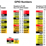
Page 2 is the pinouts for all Pi models
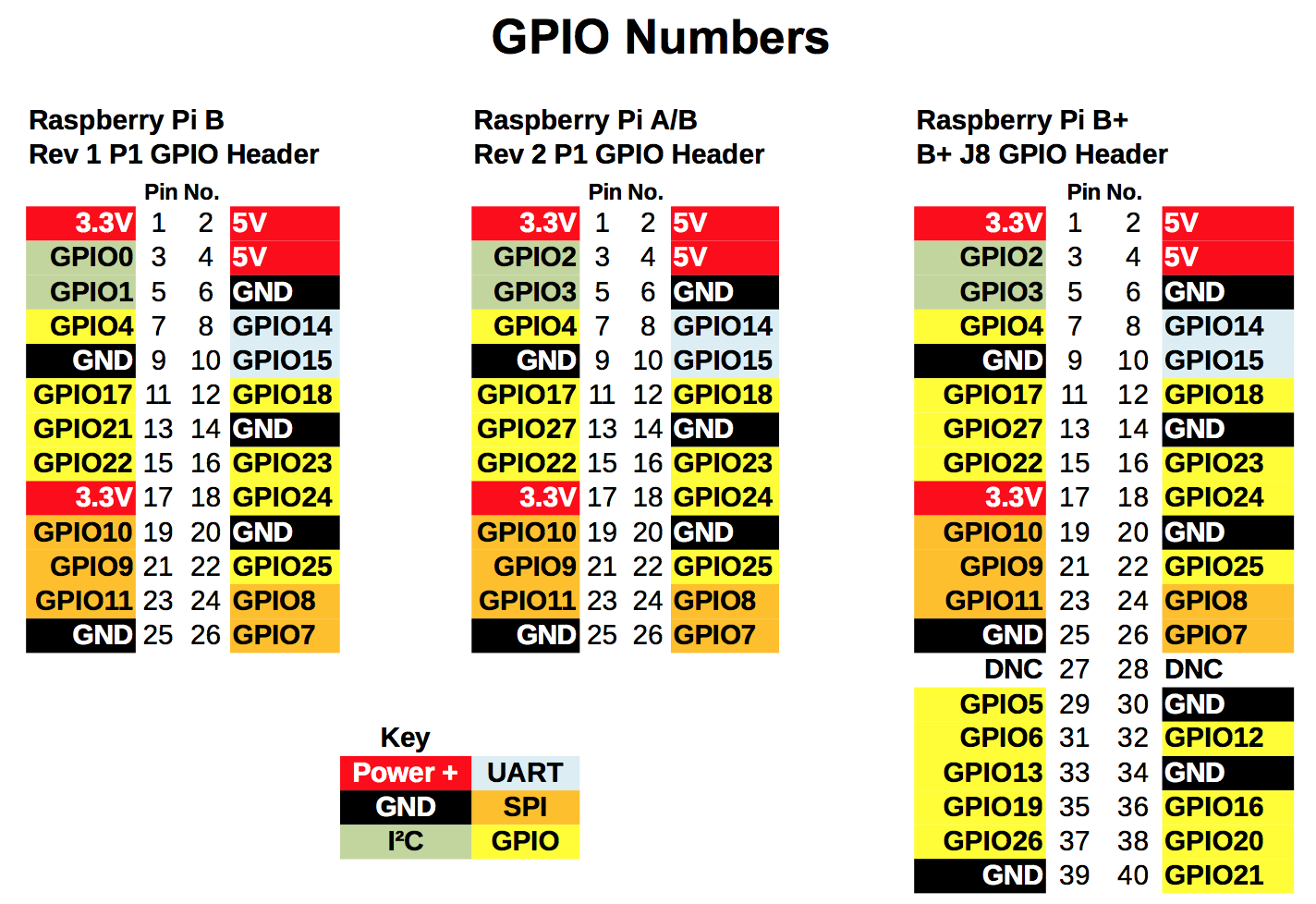
Raspberry Pi GPIO Pinouts, all models
Page 3 is an Index of Tutorial Links
RPi.GPIO Basics series
- How to check what RPi.GPIO version you have
- How to check what Raspberry Pi board Revision you have
- How to Exit GPIO programs cleanly, avoid warnings and protect your Pi
- Setting up RPi.GPIO, numbering systems and inputs
- Setting up and using outputs with RPi.GPIO
- Using inputs and outputs at the same time with RPi.GPIO, and pull-ups/pull-downs
- RPi.GPIO cheat sheet
RPi.GPIO more advanced
Interrupts (needs RPi.GPIO 0.5.2+)
- Background and simple interrupt: How to use interrupts with Python on the Raspberry Pi and RPi.GPIO
- Threaded callback: How to use interrupts with Python on the Raspberry Pi and RPi.GPIO – part 2
- Multiple threaded callback: How to use interrupts with Python on the Raspberry Pi and RPi.GPIO – part 3
- Edge Detection: Detecting both rising and falling edges with RPi.GPIO
Software PWM
From 0.5.2a onwards, RPi.GPIO has software PWM. Below are two links. One describes its basic usage and the other is a practical application for dimming LEDs and controlling motor speed.
- PWM: RPi.GPIO 0.5.2a now has software PWM – How to use it
- PWM practical: How to use soft PWM in RPi.GPIO 0.5.2a pt 2 – led dimming and motor speed control
Download Link
Hope this is useful for you.
The download here https://raspi.tv/download/RPi.GPIO-Cheat-Sheet.pdf
RasPiO® GPIO Reference Aids
Our sister site RasPiO has three really useful reference products for Raspberry Pi GPIO work...
Small errors in the B+ Alternative Functions pinout:
pin36 (GPIO16) is CE2_1
pin38 (GPIO20) is MOSI_1
(dunno if anyone’s developed a driver for SPI1 yet though?)
PWM0 is available on GPIO12 and GPIO18 (pins 32 and 12)
PWM1 is available on GPIO13 and GPIO19 (pins 33 and 35)
The RPi.GPIO documentation link is now http://sourceforge.net/p/raspberry-gpio-python/wiki/Home/
Possibly worth mentioning that GPIO.RPI_REVISION reports 0 for the Compute Module and 3 for the Model B+ ? http://sourceforge.net/p/raspberry-gpio-python/code/ci/default/tree/source/cpuinfo.c#l51
Thanks Andrew I’ve corrected the spi errors. (Dunno how that happened. Must’ve been a silly error.)
I’ve left the PWM.
Will update the Revision output on the tutorials later. :)
You’ve updated the documentation link in the PDF, but not in https://raspi.tv/download/rpigpio.txt ;-)
IMHO it’s worth adding at least one other PWM label to indicate that the Model B+ has two PWM channels on the header, whereas the Model B only has one PWM available.
OK. I did wonder what you were referring to. I hadn’t changed the .txt file at all (have now) :)
Will get to the PWM thing. Wanted a quick fix to correct the errors as I’ve already worked too hard this week and need to switch off the computer and go and have a life ;)
As far as I understand it though, the BCM only has 2 PWM channels, but both can be used if you’re not using analog sound?
“As far as I understand it though, the BCM only has 2 PWM channels, but both can be used if you’re not using analog sound?”
Yep, that’s the way I understand it too. I’ve never actively used PWM myself! (apart from “by default” when using analogue audio)
Enjoy the downtime :)
Please do not consider this criticism — your efforts are more than worthy.
Are there not some other useful pins, at least in Rev 2. Particularly, but not limited to the headers P5, which contains 4 GPIO pins as well as some power and ground pins. Header P6 also provides for a reset.
Specific References:
http://elinux.org/RPi_Low-level_peripherals#P5_header
http://elinux.org/RPi_Low-level_peripherals#P6_header
General Reference:
http://elinux.org/RPi_Low-level_peripherals#General_Purpose_Input.2FOutput_.28GPIO.29
Yes but most people don’t solder additional headers to their pi, so I’m only really bothered about documenting the main header.
As it happens, I’m the only person I know who has actually soldered both P5 and P6 headers on a Raspberry Pi.
https://raspi.tv/tag/solder-a-p6-header-on-raspberry-pi
https://raspi.tv/2013/the-leaning-header-of-pi5a-how-best-to-solder-a-header-on-p5
I did it just to try them out and then never used them again. There is only one add-on board I know about for the rev 2 that uses the P5 header (Wolfson audio card). The pins are generally so un-utilised that I’m going for the ‘thick end of the wedge’ here. I expect the new B+ design will get people using more of the pins.
“As it happens, I’m the only person I know who has actually soldered both P5 and P6 headers on a Raspberry Pi.”
Well, you know me as well https://raspi.tv/2013/the-leaning-header-of-pi5a-how-best-to-solder-a-header-on-p5#comment-27353 ;-P
I’ve actively used the P6 reset header quite a few times, but like you the P5 header was more of a “let’s see if it works” thing. And I got a IQ Audio DAC a while ago (again, just for experimentation) which comes with a female header you need to solder onto P5.
I knew you’d done P5. I remember you showed me your special push-fit connector at CamJam May 2013, but didn’t know you’d done P6 as well.
I don’t normally bother with P6 header now. If I need a reset (rare) I just short it with tweezers. :)
Well now you do know. I’m not expecting a skills badge though ;)
For one of the applications I’m working on it’s useful for one Pi to be able to able to hard-reset a second Pi if it stops responding to commands sent over the serial port (which is a pretty good indication it’s crashed / locked up).
[…] few weeks ago I blogged about RPi.GPIO updates for the model B and updated my RPi.GPIO documentation and quick reference sheets. But there was one feature I held back on because I needed a bit more time to mess about with it. […]
Thank you for creating this. Are you going to now add the CM to it ?
No. I don’t think enough people bought them for that. And most of those that did wouldn’t need it.
Although I *have* added CM and CMIO columns to http://elinux.org/RPi_BCM2835_GPIOs :-)
so, you can change inputs to outputs on the GPIO using software?!?!?
(palm, apply directly to the forehead)…i have so much to learn.
Oh yes. :)
OK. so, you have seen the face of a noob to the RPi B+. I know a lot about Linux, studied electronics back in 92/93(dating myself here….sigh), run my own company(computer hardware/software repair)…where should i start in the tree of learning on this?
I don’t want the “”N” for Dummies”(chapter one, hello world->console, chapter 2, hacking the government websites with cryptographic analyzers using asymmetrical flux capacitors).
A good solid base with alot of info would be helpful.
TYIA.
For learning how to use GPIO with Python, Alex’s tutorial links above are a pretty good start.
For other stuff, look at http://www.raspberrypi.org/help/ and http://www.raspberrypi.org/documentation/ and http://www.raspberrypi.org/community/ (especially the MagPi link).
One of the great things about Raspberry Pi is the massive community, and hence lots of user-created blogs / tutorials / etc. :-)
And of course there’s loads of books as well, if you’re looking for something more comprehensive…
http://www.amazon.co.uk/s/ref=nb_sb_noss_1/280-2037755-8724566?url=search-alias%3Dstripbooks&field-keywords=Raspberry%20Pi
Hi,
I have a question, which one of PWM1 GPIO (13 or 19) should I use?
Thx
This is a very awesome reference guide, I’m using it for my class. Thank you!
You’re welcome. Thanks for checking in. :)
Hi Alex – could you update your 40-pin header to show the SDIO bus (4 bit mode on 22-27, 1-bit mode on 22-25), which recent (> May 2015) firmwares & drivers have made available. This bus has decent (for the Pi) ~200Mbps bandwidth, useful to attach extra SD card storage or SDIO peripherals eg WiFi. That would leave fewer yellow pins, but by showing it it might help designers of future HATs to keep off SDIO territory unless absolutely essential.
Oooh, even I wasn’t aware of that – I must be falling behind ;-) I guess that must be using the SD1_* signals on http://elinux.org/RPi_BCM2835_GPIOs ?
AFAIK Alex made his diagrams for home-user GPIO-tinkerer hobbyists though, not HAT-designers… :)
Yes, those pins. The 2835/6 contain two peripherals which support SD cards – one which has lain dormant until PhilE wrote a driver for it, namely the sdhost peripheral, which is latterly providing SD card duties for the Pi. The previously used peripheral, the emmc block from Arasan has been retired to SDIO duties available on GPIOs 22-27.
The “get off my lawn” message needs to get out there somehow! I’m a tinkerer, doesn’t stop me designing my own SDIO !HAT though, inspired by this brilliant piece of hacking https://hackaday.io/project/8678-rpi-wifi
“inspired by this brilliant piece of hacking…”
Ah, that’s rather excellent! Will have to get some modules and try that :-)